8 November 2021 by Phillip Johnston • Last updated 16 November 2021A Structural System Context Model is a type of system context model that models the interactions between the total system (hardware + software) and its external environment. Purpose This model helps us define the boundary between the total system (hardware + software) and its external environment. Each actor in the environment Structural modeling of the System (Hardware/software) context Defines boundary between total system (hardware and software) and external environment This model can be used to generate a Software System Context Model for the system. The system is decomposed into …
A Software System Context Model is a type of system context model that explicitly depicts the boundary between the software system and its external environment: the hardware devices that the software system interacts with in order to engage with the environment.
Purpose
This model helps us determine the boundary between hardware and software blocks in our system. It also helps us determine the number and makeup of hardware devices required by the software system.
Useful Inputs
If you have a Structural System Context Model, creating the Software System Context Model becomes a simple decomposition exercise. The total hardware/software system is decomposed into a total software system that interacts with hardware components. These hardware components interact with the external elements shown in the Structural System Context Model.
Guidelines for Creation
We often create system context models using SysML block definition diagrams. Standard UML class diagrams can also work for this purpose.
In Real-Time Software Design for Embedded Systems, Hassan Gomaa provides formal guidelines for creating software system context models using specific UML stereotypes and entity relations. We use these guidelines as the starting point for our own models, although we may extend the initial set of stereotypes and relations if our system context model would benefit.
The system being designed is represented in this diagram as a single aggregate block marked with the «software system» stereotype
Since the software system cannot interact directly with external physical entities, we need to have sensors, actuators, and other hardware devices that our software system can use to interact wit the external world
All remaining «external» blocks in this diagram are depictions of the hardware components that the software system interacts with:
«external device», which can be further decomposd into:
«external input device» – a device that provides only input to the system (e.g., a sensor)
«external output device» – a device that receives only output form the system (e.g., an actuator, a heating element)
«external input/output device» (or «external I/O device») – a device that provides both inputs to the system and receives outputs from the system (e.g., a card reader for an ATM)
«external user» – models a human user who interacts with the system by means of standard I/O devices such as a keyboard/display and mouse
A general guideline proposed by Gomaa is to represent a human user as an «external user» block only if the user interacts via standard I/O devices. If the user interacts with the system via application-specific I/O devices, these devices should instead be represented as «external I/O» blocks
We always model «external user» interactions as I/O devices
«external timer» – used if the application needs to keep track of time and/or if it needs timer events to initiate specific system actions
«external system» – needed when the system interfaces to other systems, to either send data or receive data
These blocks may also be decomposed into specific «external device»s that model the actual communication channel
In addition, our software system context diagram models the associations between the system and external elements. Gomaa again provides standard association names that we like to use as a starting point for embedded system design:
Inputs to
Outputs to
Communicates with
Interacts with
Signals
From the software perspective, some external blocks on the Structural System Context Model will be modeled in the same way on the Software System Context Model, while some are modeled differently.
«external system» and «external user» blocks will interact with the system using standard I/O devices and may be represented the same way in this model as on the Structural System Context Model (we always model these interactions as I/O devices, regardless of their generality)
«external physical entities» are not physically connected to the system and need sensors and actuators to make the physical connection to the system so the software can interact with it. Hardware devices are needed: detection of physical entities is done with sensors, control of physical entities is done with actuators.
Example Associations
Here are example associations between elements that use Gomaa’s stereotypes:
«external input device» Inputs to «software system»
«software system» Outputs to «external output device»
«external user» Interacts with «software system»
«external system» Communicates with «software system»
«external timer» Signals «software system»
Examples
This example of a railroad crossing system comes from Real-Time Software Design for Embedded Systems by Hassan Gomaa. Note the use of Gomaa’s recommended relations and UML stereotypes:
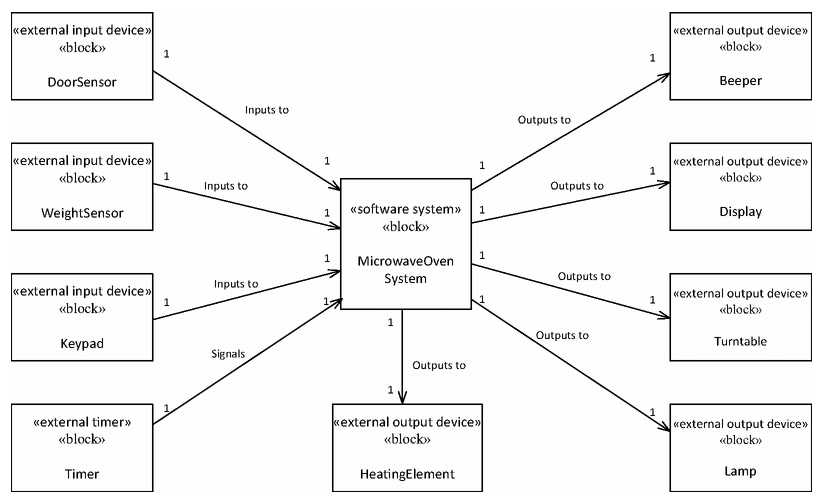
This example of a microwave oven system comes from Real-Time Software Design for Embedded Systems by Hassan Gomaa. Note the use of Gomaa’s recommended relations and UML stereotypes:
The following file is a hand-drawn software system context model that we created when first conceiving of the Embedded Virtual Machine project. Note that this particular diagram did not provide very much value for this particular system, so we did not focus heavily on it.