
Today we have a guest post from Silard Gal, an embedded systems designer. He has worked on many prototypes for companies around the World and his focus now is smart city hardware and software. You can contact him via LinkedIn.
Your new IoT device is ready. It’s finally booting, communicating, and reading sensors. You feel awesome!
Then you decide to test it with a battery, and you suddenly notice you’re only getting 10% of your expected battery life. You are starting to get nervous, and then the device suddenly drops dead… Time to roll up your sleeves and get to work!
This post will cover everything you need to know about battery power optimization, including common mistakes, tips, and tools that you can use to make your device live up to your battery life goals.
Parts of a Power System
All power systems have a rated amperage, voltage and efficiency. IoT devices typically focus on low amperage and low voltage, and high efficiency to achieve a long battery life.
A power system can be modeled with the following components:
Regulator
The regulator steps down or boosts your battery voltage to a voltage that is acceptable by your device. Regulators come in various sizes and form factors. It’s important for them to be acceptable to your budget, capable of delivering sufficient current to the device, have a low quiescent current, and operate at high efficiency.
The budget depends on the quality of the regulator you are using. Some applications require high quality regulators (e.g., analog circuits, where low noise is an important characteristic), but there are also applications where you can use a cheap regulator.
Quiescent current is the silent killer in every IoT application, so it’s important to select a regulator with a low quiescent current. Acceptable quiescent currents run around 5-15uA. It’s important to note that quiescent currents change depending on device temperature. For example components, see ST’s low quiescent regulators.
Typical efficiency numbers are around 80-90%, but for an IoT applications, it’s important to aim for >90% efficiency. An example component that can meet this goal is the ADP1147, which can deliver up to 95% efficiency.
Battery
Your battery provides energy to your portable device. Batteries come in various forms. An extremely popular choice is a 18650 3.7V Li-Ion battery cell.
If the situation is convenient, it’s preferred to choose the battery last. After choosing your regulators and calculating your consumption it’s easy to choose the best budget and most-efficient battery for your device. It’s also important to note that batteries should be chosen depending on power needs of the device.
For example: Let’s say our battery life target is 1 year. Our calculations show an average consumption of 57uA. We can comfortably select a 500mAh battery.
1 year = 8760 h
500 mAh = 500.000 uAh
500.000 uAh / 57 uA = 8771h
Load
An electric load is a device that consumes electric power. For most IoT devices, the load will consist of an MCU, sensors and a way to communicate with the outside world. Newer technologies have introduced SoC’s, which combine an MCU with a communication transceiver, lowering consumption and space on the PCB.
For example: there is the new STM32WLE5 MCU that combines an STM32L4 architecture with existing LoRa transceivers.
The details for each component in the load greatly impact the battery life of your device.
Tool for Measuring Power Consumption
Analyzing and measuring your current consumption is a must when optimizing your device. A multimeter is good enough to measure current, but it’s way easier to consider devices like the Otii for making power measurements.
Devices like that add the ability to measure current, set voltage and simulate batteries, while monitoring everything from your PC. The software can analyze and give back very detailed data on your consumption. Extra features are programmable pins that can act as interrupt wake up pins.
A professional approach is a Keysight analyzer that delivers 0.1 fA – 1A and 0.5 µV – 200 V ranges.
Tips for Improving Battery Life
We will cover 7 tips that help you identify holes in your power system. This list can even act as a basic checklist for power optimization.
- Create a Battery Budget
- Set I/O to Low Power
- Use Processor Power Modes
- Turn off Unused Processor Peripherals
- Control External Peripheral Power
- Optimize Program Flow
- Increase Clock Speed to Finish Processing Faster
- Use a Buck Converter or LDO
Tip #1 – Create a Battery Budget
Creating a battery budget is very important and should be done at the beginning of the project, because you will see if the battery life you are expecting matches the battery life you will actually get. If the numbers don’t match, you haven’t wasted much time and can start over easily by choosing other components and re-calculating your battery life.
When determining a battery budget, you have to look at your desired power management system and choose the best part for your budget and the corresponding efficiency numbers.
Battery Budget Checklist
- List all your components
- Write down the active and low power current consumption
- Preferably, you will measure these values on your own form-factor board or development board
- Estimated consumption numbers can be calculated using values sourced from the devices datasheet
- Determine the time your device will be in active and low power modes
- This can be a challenge for some projects. If average numbers are not known, it’s best to estimate the worst case scenario.
- This time can be presented in seconds, milliseconds or % of the day.
- Calculate average current consumption by adding up all the active and low power mode consumption numbers and dividing it by the summed up time.
(ActiveCurrent∗TimeInActive+SleepCurrent∗TimeInSleep)/(TimeInActive+TimeInSleep)
- Determine your battery size. To get the required mAh, multiply your average current with your target operational time. Always choose a higher mAh rating than your desired one.
- Calculate the estimated battery life, which is
Battery[mAh]/AverageConsumption[mA]=BatteryLife[h]
A standard battery budget will look something like this.
Tip #2 – Set I/O to Low Power
All datasheets include a section that describes the I/Os (example in the ATMega328P datasheet link). Putting your I/Os into a low power mode is preferable, because it blocks very small amounts of current from escaping (called leakage). A good article to learn more about leakage can be found here.
It is important to note that most MCUs come with I/Os already turned off at boot, meaning it’s set as an input, disconnected from the input buffer and the pull-up resistor is disabled.
The primary goal is to ensure current isn’t flowing into or out of the GPIO when we’re sleeping or not using a component. The exact settings you want to use are going to be system-dependent.
For example, high-Z inputs will work for some situations (e.g., GPIO is expected to be low), but it may also cause a particular signal to float, causing a peripheral to unexpectedly draw current. If a signal defaults to 3.3V and must be driven low to active a part, that GPIO will need to be set as an input with a pull-up enabled. Also note that your peripherals may have internal pull-ups/pull-downs that you may need to account for.
Here are rules of thumb that you can follow as a starting point for GPIO settings:
- If the peripheral’s I/O output is low in the target mode, then ensure that the GPIO is programmed either as an input without pull-up/down (high-Z) or as an input with pull-down. Confirm exact usage by monitoring power consumption to ensure you don’t need the pull-down.
- If the peripheral I/O output is high in the target mode, then ensure that the GPIO is programmed either as an input without pull-up/down (high-Z) or as an input with pull-up. Confirm exact usage by monitoring power consumption to ensure you don’t need the pull-up.
You can check current draw through pull-up / pull-down resistors on your board to ensure there is no unexpected current drain through the resistors when in low-power states. Use this technique to confirm that your GPIO optimizations are having the expected effect.
Also note that some processors may have standby modes that can be configured which automatically change the GPIO state when the power mode changes. Check your processor’s datasheet to see if you can utilize this feature.
Tip #3 – Use Processor Power Modes
Every MCU provides different power modes. Commonly provided power modes are “active”, “sleep”, and “deep sleep”.
Every mode comes with it’s own current consumption rating, transition time, list of peripherals that are enabled. Sleep and deep sleep modes will also specify a method for waking up the processor.
For example, the STM32L supports the following power modes:
- Sleep Mode: CPU core is stopped, RAM & register contents are retained, specific chosen peripherals are active. The CPU can be woken up by any of the active peripherals. Current consumption drops to 400uA – 1mA at 16 MHz clock rate.
- Low Power Sleep Mode: CPU core is stopped and the active peripherals are limited, depending on what is active. The CPU will wake up from an RTC interrupt. Current consumption drops to 3.2uA.
- Stop Mode: The CPU core is stopped but RAM and register contents are retained. Most of peripherals are stopped.
- Stop Mode with RTC : Wake-up is an external signal or RTC interrupt. Current consumption drops to 0.8uA.
- Stop mode without RTC : Wake-up is only an external signal, and the RTC is stopped. Current consumption drops to 0.38uA.
- Standby Mode: The CPU core is stopped, registers & RAM are stopped.
- Standby with RTC: Wake-up is external or RTC. Current consumption drops to 0.57uA
- Standby without RTC : The RTC is stopped also. Current consumption drops to 0.26uA
It’s important to note that some processors will have power settings/modes, but others will control their power consumption by increasing/decreasing their clock speed.
Tip #4 – Turn off Unused Processor Peripherals
Unused peripherals are simply wasting power. Make sure you disable them at boot. You will also want to disable peripherals whenever they are not actively being used by the system.
Tip #5 – Control External Peripheral Power
Just like we want to turn off processor peripherals, we also want to be able to control the power state of external peripherals on our board. Prefer to select sensors that either have an enable pin or can be set into sleep mode.
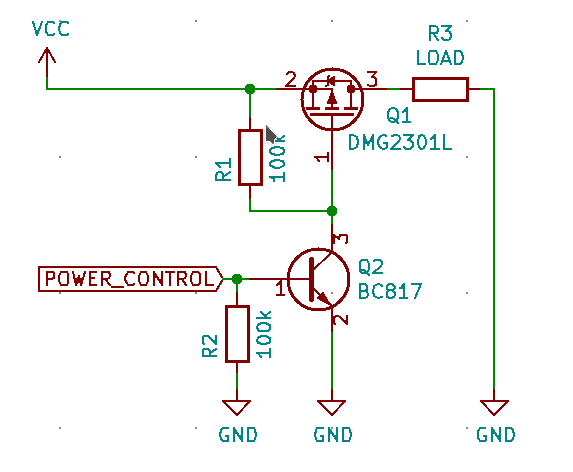
If your sensor doesn’t support these functions, you can use a simple switch (like the DMG2301L P-CHANNEL enhancement mode MOSFET) to cut the power to your sensors whenever they aren’t being used.
Here is an example schematic. In this example, a MOSFET and a transistor are used to switch power to the LOAD. In your application, the load will be the external peripheral.
Tip #6 – Optimize Program Flow
We want to optimize our application so that we are spending as little time as possible in the MCU’s “active” mode. How you accomplish this is highly application-dependent. It might mean simplifying calculations, batching operations, selecting alternate low-power communication protocols, or simply collecting data and processing it on another (higher-powered) device.
Our ultimate goal is for the device to only execute code when there is work to do. One way to achieve this is by transitioning to an asynchronous and interrupt-driven design. This is a significant advantage over the common “loop” driven approach, where a device needs to regularly wake up and poll all of the necessary sensors. Instead of polling devices, interrupts notify us whenever there is an event that we need to respond to.
For example, we can program our processor to monitor for a GPIO interrupt event, which is tied to the INT pin of a LIS3MDLmagnetometer. When the magnetometer detects a value above the programmed threshold, it sets the INT pin to high, triggering a wake-up event on our MCU. We no longer need to have the MCU wake-up periodically to poll the sensor status.
Note that this tip requires support on the hardware side. Select components that provide an interrupt line, and make sure that the line is actually connected to the processor and used by your software.
Tip #7 – Increase Clock Speed to Finish Processing Faster
Increasing the clock speed of your CPU means that you will execute your algorithm(s) faster.
It’s a logical conclusion that by increasing clock speed, you increase the power consumption of your device. However, at the same time you decrease the time that your processor is spending in the “active” state.
Every processor has a section in their datasheet describing it’s timing (example for the ATMEGA328P) and it’s consumption per MHz (example for STM32L072x8, “Down to 93 µA/MHz in Run mode”)
To estimate the tradeoff for increasing the clock rate, you have to calculate how much time it takes to execute your algorithm(s) depending on the current clock rate. After making these measurements, you can multiply the execution time by the consumption per MHz. You might find that it’s more power efficient to run at a higher clock rate to minimize time in the “active” state.
Tip #8 – Use a Buck Converter or LDO
An low-dropout (LDO) linear regulator converts excess power into heat. An LDO is a perfect fit if:
- Efficiency is not important (most LDOs go around 60-80% efficiency)
- Heat is not a problem
- Vin is slightly higher than Vout
- Current is small (under 1A)
- Your budget is low
- Need for smaller board size
A buck converter stores the power in the inductor, providing 80-95% efficiency, but it takes up more space on your board and from your budget. It must be noted that a buck converter shouldn’t be put near sensitive analog circuitry due to the electrical noise it will generate.
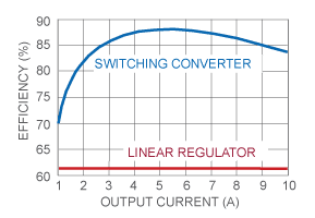
Comparing Buck & LDO Efficiencies
Efficiency differences between LDOs and Bucks can be viewed here:
We can estimate the efficiency of an LDO with a straightforward calculation. A system where the Vin is 4.2V, Vout is 3.3V and the current is 250mA, the formula used for calculations is :
P=(Vin−Vout)∗IP=(Vin−Vout)∗I
(4.2V−3.3V)∗250mA=0,225W(4.2V−3.3V)∗250mA=0,225W.
The efficiency is calculated with:
Efficiency=(Vout/Vin)∗100Efficiency=(Vout/Vin)∗100
(3.3V/4.2V)∗100=78,57(3.3V/4.2V)∗100=78,57
With the same values a buck converter like the ADP1147 is showing in its datasheet on the ‘Efficiency vs. Load Current’ graph a value of 92.5% for efficiency.
Closing Thoughts
Optimizing your device’s power consumption is not just about providing a longer battery life for your device. You are also reducing maintenance costs (associated with replacing the batteries) and giving yourself an advantage over your competition.
With newer technologies coming to surface, there is always the possibility to further lower the consumption. As always, whether it makes sense to deploy these options depends on your application, budget and time.
Further Reading
Fore more on lowering your device’s power consumption: