
17 August 2023 by Phillip Johnston • Last updated 22 August 2024I thoroughly enjoyed Architecture Anti-Patterns: Automatically Detectable Violations of Design Principles, by Mo, Cai, Kazman, Xiao, and Feng. It’s worth reading in its entirety if you are interested in their methods, but you could also just get value from reviewing the description of the architectural anti-patterns or reading the first 2 pages (which I further summarize below). Abstract In large-scale software systems, error-prone or change-prone files rarely stand alone. They are typically architecturally connected and their connections usually exhibit architecture problems causing the propagation of error-proneness or change-proneness. In this paper, we …
Problem Domain Context Model
16 November 2021 by Phillip JohnstonA Problem Domain Context Model is a type of system context model that is used to explore the problem space and environment for the system to be developed. Purpose This model is used to explore the problem domain and identify various real-world and information structural elements that are included in the problem domain. Relationships between different elements in the problem domain are also explored. The goal is to create conceptual static model which includes relevant systems, users, physical entities, and information entities Note A Rich Picture is similar in concept to a Problem Domain Context …
Continue reading “Problem Domain Context Model”
Static Models
16 November 2021 by Phillip Johnston • Last updated 1 December 2021A static model defines the structural elements of a system as well as the attributes of the elements and the relationships between elements. The structural elements are usually defined in terms of “blocks” in the total hardware/software system and “classes” in a software system. Relationships in Static Models The three main types of relationships between structural elements are: Association relationships Whole/part relationships Generalization/specialization relationships Examples of Static Models SysML Block Diagrams UML Class Diagrams System Context Models References Real-Time Software Design for Embedded Systems by Hassan Gomaa, Section 5.1 …
Continue reading “Static Models”
Rich Picture
16 November 2021 by Phillip JohnstonA Rich Picture is a method for defining and exploring a given “situation” through diagrams. They are particularly useful for depicting complex situations with multiple components and interactions. Ruth Malan often refers to rich pictures as “sketchprototypes”, since they allow you to try out different ways that the situation may play out, in different settings, with different potential solutions. Estimated duration: 30-120 minutes Purpose Rich pictures are usually drawn during the exploratory stages of a project, before we know much about the system we’re building. Rich pictures allow us to work informally and quickly to …
Continue reading “Rich Picture”
System Context Models
10 November 2021 by Phillip Johnston • Last updated 16 November 2021A system context model, also called a context view, is a static model that describes the relationships, dependencies, and interactions between a system and its environment. The system is usually modeled as either a single element or a reduced set of elements, and the environment is modeled as the people, systems, external entities, and processes that the system interacts with. System context models serve as starting points for the system design process. They help us see the role of the system in its environment at a glance, identify what …
Continue reading “System Context Models”
Structural System Context Model
8 November 2021 by Phillip Johnston • Last updated 16 November 2021A Structural System Context Model is a type of system context model that models the interactions between the total system (hardware + software) and its external environment. Purpose This model helps us define the boundary between the total system (hardware + software) and its external environment. Each actor in the environment Structural modeling of the System (Hardware/software) context Defines boundary between total system (hardware and software) and external environment This model can be used to generate a Software System Context Model for the system. The system is decomposed into …
Continue reading “Structural System Context Model”
Software System Context Model
A Software System Context Model is a type of system context model that explicitly depicts the boundary between the software system and its external environment: the hardware devices that the software system interacts with in order to engage with the environment.
Purpose
This model helps us determine the boundary between hardware and software blocks in our system. It also helps us determine the number and makeup of hardware devices required by the software system.
Useful Inputs
If you have a Structural System Context Model, creating the Software System Context Model becomes a simple decomposition exercise. The total hardware/software system is decomposed into a total software system that interacts with hardware components. These hardware components interact with the external elements shown in the Structural System Context Model.
Guidelines for Creation
We often create system context models using SysML block definition diagrams. Standard UML class diagrams can also work for this purpose.
In Real-Time Software Design for Embedded Systems, Hassan Gomaa provides formal guidelines for creating software system context models using specific UML stereotypes and entity relations. We use these guidelines as the starting point for our own models, although we may extend the initial set of stereotypes and relations if our system context model would benefit.
- The system being designed is represented in this diagram as a single aggregate block marked with the
«software system»stereotype - Since the software system cannot interact directly with external physical entities, we need to have sensors, actuators, and other hardware devices that our software system can use to interact wit the external world
- All remaining
«external»blocks in this diagram are depictions of the hardware components that the software system interacts with:«external device», which can be further decomposd into:«external input device»– a device that provides only input to the system (e.g., a sensor)«external output device»– a device that receives only output form the system (e.g., an actuator, a heating element)«external input/output device»(or«external I/O device») – a device that provides both inputs to the system and receives outputs from the system (e.g., a card reader for an ATM)
«external user»– models a human user who interacts with the system by means of standard I/O devices such as a keyboard/display and mouse- A general guideline proposed by Gomaa is to represent a human user as an
«external user»block only if the user interacts via standard I/O devices. If the user interacts with the system via application-specific I/O devices, these devices should instead be represented as«external I/O»blocks - We always model
«external user»interactions as I/O devices
- A general guideline proposed by Gomaa is to represent a human user as an
«external timer»– used if the application needs to keep track of time and/or if it needs timer events to initiate specific system actions«external system»– needed when the system interfaces to other systems, to either send data or receive data- These blocks may also be decomposed into specific
«external device»s that model the actual communication channel
- These blocks may also be decomposed into specific
In addition, our software system context diagram models the associations between the system and external elements. Gomaa again provides standard association names that we like to use as a starting point for embedded system design:
- Inputs to
- Outputs to
- Communicates with
- Interacts with
- Signals
From the software perspective, some external blocks on the Structural System Context Model will be modeled in the same way on the Software System Context Model, while some are modeled differently.
«external system»and«external user»blocks will interact with the system using standard I/O devices and may be represented the same way in this model as on the Structural System Context Model (we always model these interactions as I/O devices, regardless of their generality)«external physical entities»are not physically connected to the system and need sensors and actuators to make the physical connection to the system so the software can interact with it. Hardware devices are needed: detection of physical entities is done with sensors, control of physical entities is done with actuators.
Example Associations
Here are example associations between elements that use Gomaa’s stereotypes:
«external input device»Inputs to«software system»«software system»Outputs to«external output device»«external user»Interacts with«software system»«external system»Communicates with«software system»«external timer»Signals«software system»
Examples
This example of a railroad crossing system comes from Real-Time Software Design for Embedded Systems by Hassan Gomaa. Note the use of Gomaa’s recommended relations and UML stereotypes:

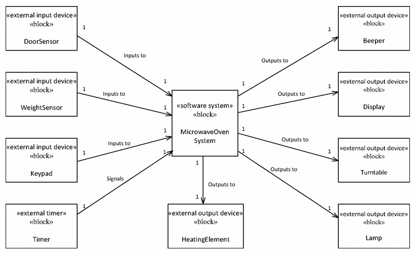
This example of a microwave oven system comes from Real-Time Software Design for Embedded Systems by Hassan Gomaa. Note the use of Gomaa’s recommended relations and UML stereotypes:
The following file is a hand-drawn software system context model that we created when first conceiving of the Embedded Virtual Machine project. Note that this particular diagram did not provide very much value for this particular system, so we did not focus heavily on it.
Related
- This model is used in the Embedded Artistry Development Process stage: System Context Modeling
- This model is a type of System Context Model
- This model is often a direct decomposition of a Structural System Context Model
References
- Real-Time Software Design for Embedded Systems by Hassan Gomaa, Section 5.5 and 5.6
Embedded Artistry’s Software Layering Strategy
In our standard embedded software design approach, we use a layered architecture that decomposes into four primary layers:
- Processor Layer, which abstracts the underlying processor used by the target platform
- Hardware Platform Layer, which abstracts the underlying circuit board and provides board-level abstractions for use by the platform layer
- Platform Layer, which abstracts the underlying circuit board, operating system, and C/C++ runtime
- Software Layer, which sits atop the Platform Layer, which allows it to be portable across platforms (given that requirements are met by the platform implementation)
In addition, there is a cross-cutting Utilities “layer” which is independent of the target platform & architecture. The Utility constructs are usable by all layers.
The primary goal of this layering strategy is to create re-usable and portable device drivers and software constructs for embedded devices and product lines. In order to achieve this goal, the software and hardware segments must be decoupled and interchangeable at the three layering points.
Visual Representation
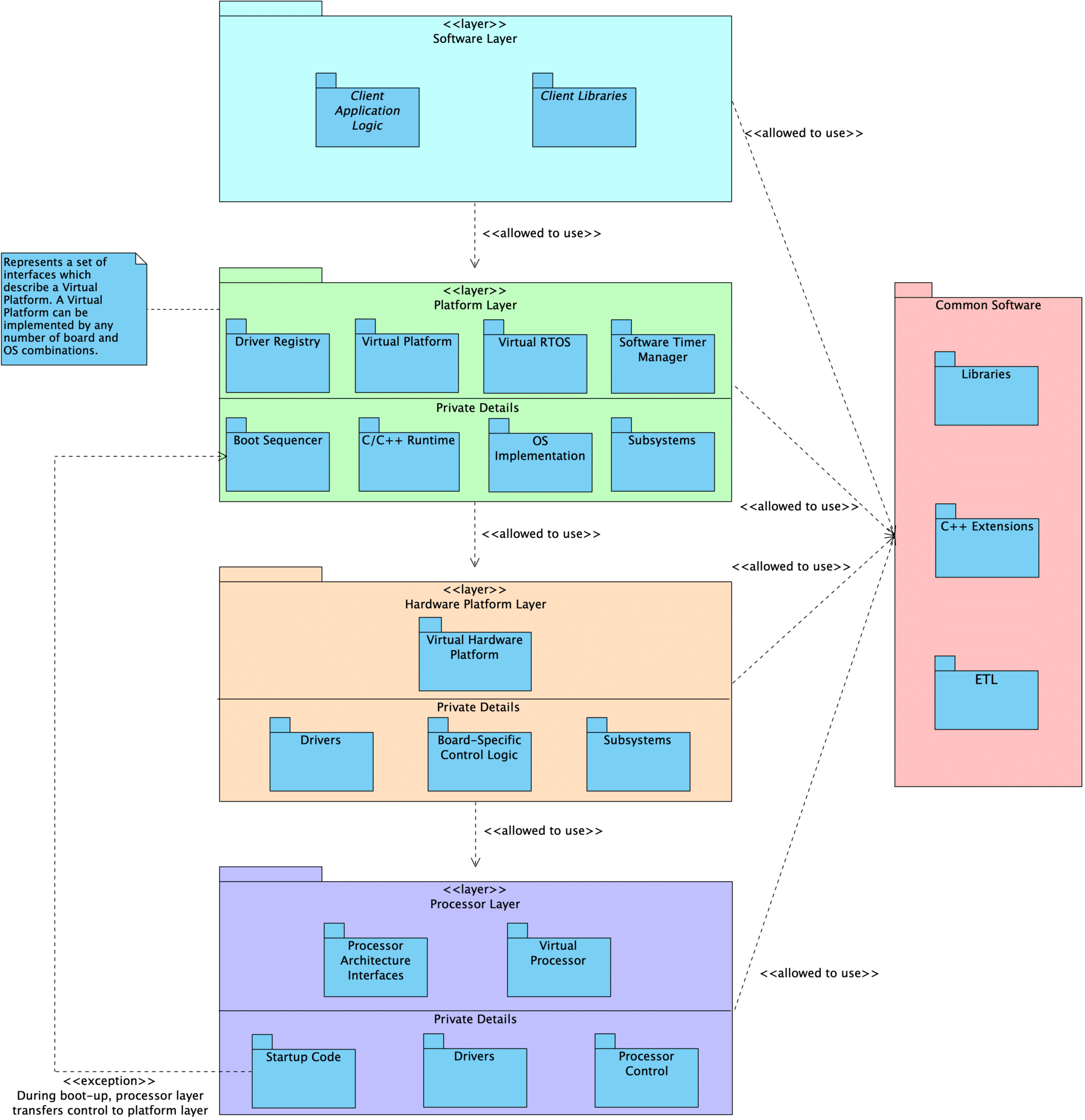
Layer Description
Processor
At the core of an embedded program is the Processor layer. This layer includes the processor peripheral drivers and processor control module. Every processor is unique in its makeup of peripherals, capabilities, and the interfaces we provide.
We define an abstracted Facade interface that can be used to interact with the Processor as a singular subsystem. This interface provides functionality such as init() and reset(). Code that interacts with the abstract Facade interface never needs to be updated when we change from one processor to another.
Note: The processor is the biggest source of coupling in embedded programs and presents the most difficulty when we are required to migrate from one processor to another. Ultimately, we don’t want our application layer to know anything about the processor itself.
Hardware Platform
Above the Processor sits a HardwarePlatform, which serves as a both a Facade and a Mediator for the complete hardware subsystem.
The responsibilities of this layer include:
- Declaration of the system’s
Processorand the necessary processor peripheral drivers - Declaration of drivers for external peripheral components
- Configuring all peripherals
- E.g., configure
SPI0to useDMA1, time-of-flight sensor is connected toI2C0on board revision A andI2C1on revision B
- E.g., configure
- Providing standard interfaces used to interact with the underlying hardware at a broad level
- E.g., APIs to change power state, reset the board, set the LEDs to indicate an error
User code interacts with the hardware using the HardwarePlatform interfaces rather than directly talking to the specific hardware components.
Hardware subsystem components (such as i2c1 or tof0) can also be accessed by the rest of the program through virtual device interfaces that are common to all components of that category. Inside of the HardwarePlatform layer, we know the exact types and configuration details for the underlying modules. We can call all of the available interfaces provided by each unique processor and driver type. However, outside of the HardwarePlatform, users are restricted to generic driver interfaces (e.g., i2cMaster instead of nRF52I2CMaster or aardvarkI2CMaster).
In this way, the coupling to drivers and processor peripherals is contained in a single location rather than spread throughout the code base. Client code is only weakly coupled to the underlying hardware through the use of the generic virtual device interfaces and the HardwarePlatform Facade interfaces. When we change our processor or select a different external peripheral, we only need to update the HardwarePlatform.
Platform
The next layer up is the Platform layer. We can imagine that a Platform is the sum of the underlying HardwarePlatform, the chosen operating system (or lack of one), the language standard library, and other supporting constructs that our application depends on. Similar to the HardwarePlatform, we use the Platform as a Facade/Mediator by providing a standard abstract interface.
Application logic can only use the interfaces provided by the Platform layer, as well as generic driver interfaces for hardware installed on the board. In this way, the application logic is prevented from being tightly coupled to the specific hardware and platform details. We are free to run our application on any Platform that fulfills its requirements.
Seeing it In Action
This layering scheme is defined in the emvbm-core project. We have example projects built using this strategy:
- embvm/blinky contains the application layer code for a simple
blinkyexample. This project runs on a personal computer using an Aardvark adapter hooked up to an LED, an nRF52840 development kit, an nRF USB Dongle, and an STM32 NUCLEO-L4R5ZI development board. - embvm-demo contains a more complicated example application involving LEDs, a time-of-flight sensor, and an OLED display. This application runs on a personal computer using an Aardvark adapter, an nRF52840 development kit, and an STM32L4R5ZI-P Nucleo development kit.
- embvm-demo-patforms contains example platforms and hardware platforms that are shared by our blinky and embvm-demoprojects
- stm32l4 provides an example hardware platform, platform, and blinky application that will run on an STM32 NUCLEO-L4R5ZI development kit.
References
- embvm-core Documentation: Architectural Layer View describes this layering scheme in much more detail, with explanations given to each element
- For information on how we use our build systems to enforce the layering described above, see Leveraging Our Build Systems to Support Portability
- Managing Coupling with the Mediator and Facade Patterns presents this information in the context of the design patterns that inspired this scheme
- Virtual Devices in Embedded Systems Software