
In Leveraging Our Build Systems to Support Portability, I described techniques we can use for enforcing the use of proper abstractions in our embedded programs. By using these techniques, we place ourselves in a better position to respond to changes in the underlying hardware. Components can be quickly swapped out, and code changes are only made in areas where tight coupling is allowed. The rest of the system interacts with generic interfaces, meaning that code does not need to change.
This article prompted a question from a reader:
Great entry, as always. Something is not clear to me yet (probably because I haven’t seen the rest of the code): In the examples above you are using two classes named
nRF52840andFreeRTOSMutex, which I guess inherit from a virtual class likeProcessorandMutex. My question is, how do you use them in the application code? I guess at some point you have to initialize aMutexobject and inject theFreeRTOSMutexor thePOSIXMutexdepending on what the target platform is. Where and how do you do this? Can you give an example?
I will be exploring various ways to approach this on the website. To start the discussion, I want to review two foundational design patterns that inspire our approach to designing embedded software for change: Mediator and Facade.
Table of Contents:
- Mediator Pattern Explained
- Facade Pattern Explained
- Differentiating the Patterns
- Applicability for Embedded Projects
- Putting it All Together
- Further Reading
Mediator Pattern Explained
I first came across the Mediator pattern in Design Patterns: Elements of Reusable Object-Oriented Software, also known as the “Gang of Four” book. They describe the intent of the pattern as:
Define an object that encapsulates how a set of objects interact. Mediator promotes loose coupling by keeping objects from referring to each other explicitly, and it lets you vary their interaction independently.
The text goes on to say:
You can avoid these [dependency] problems by encapsulating collective behavior in a separate mediator object. A mediator is responsible for coordinating and controlling the interactions of a group of objects. The mediator serves as an intermediary that keeps objects in the group from referring to each other explicitly. The objects only know the mediator, thereby reducing the number of interconnections.
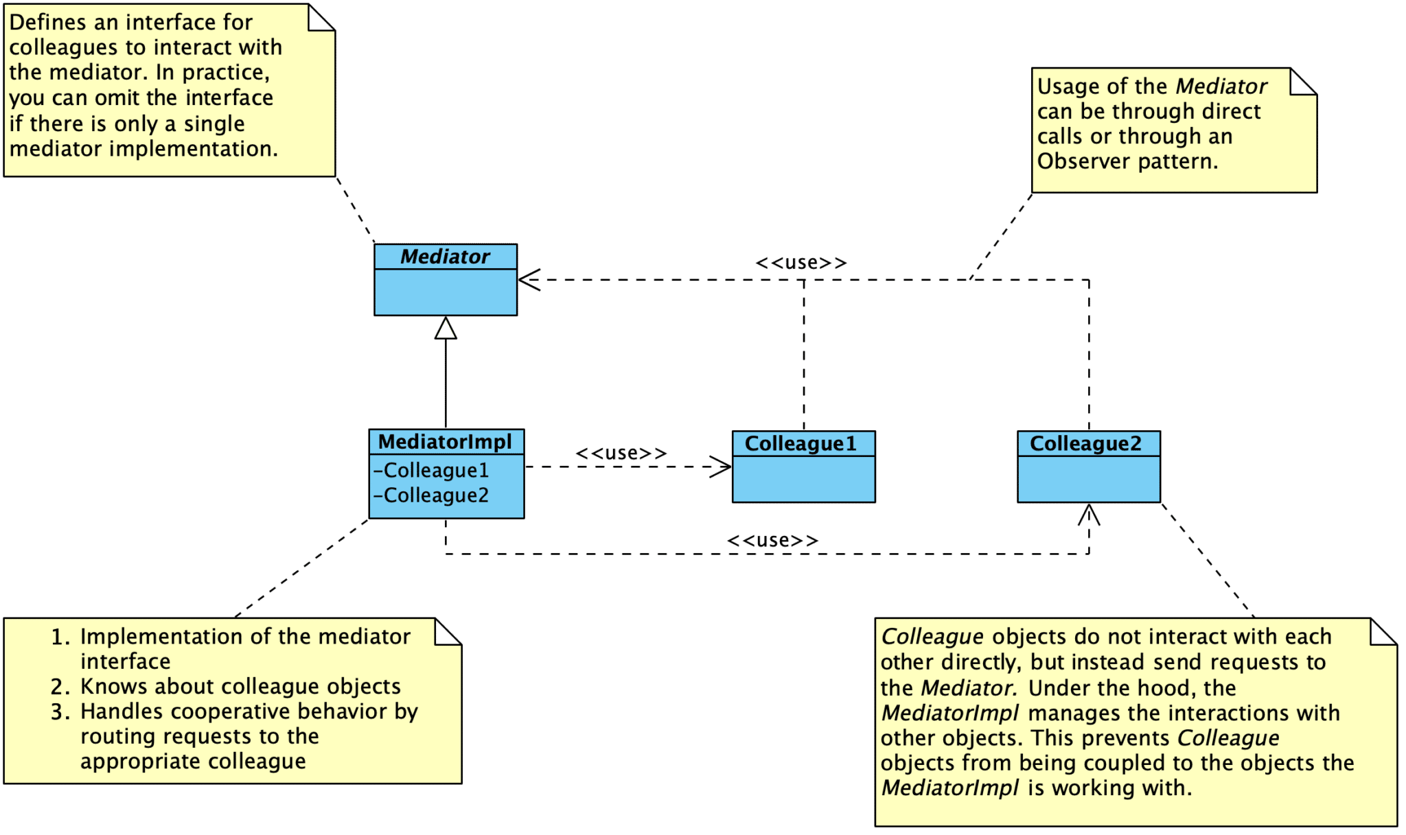
The goal of this pattern is to decouple objects by constraining their interactions within a single Mediator. Instead of having objects interact with each other directly, the Mediator is responsible for coordinating the interactions between objects. Colleague objects know about the Mediator, but do not know about each other. The Mediator manages all interactions among Colleague objects.
This approach has three primary benefits:
- Interactions between objects are managed in a single place, instead of distributed across several objects. Changes in how objects interact only impact the Mediator. This also helps us focus on interactions separately from the individual behavior of the objects.
- We create a one-to-many interaction set between the Mediator and its colleagues. This is much easier to conceptualize and manage than many-to-many interactions distributed among objects.
- Colleague objects are easier to reuse in other systems due to the reduced dependencies on other modules. We can independently reuse and vary the Mediator and its Colleagues.
One tradeoff with using the Mediator pattern is that we push most of the complexity in object interactions into the Mediator itself. The Mediator runs the risk of becoming overly complex, but this can be managed.
Facade Pattern Explained
The Facade pattern is also described in the Design Patterns book. They describe the intent of the pattern as:
Provide a unified interface to a set of interfaces in a subsystem. Facade defines a higher-level interface that makes the subsystem easier to use.
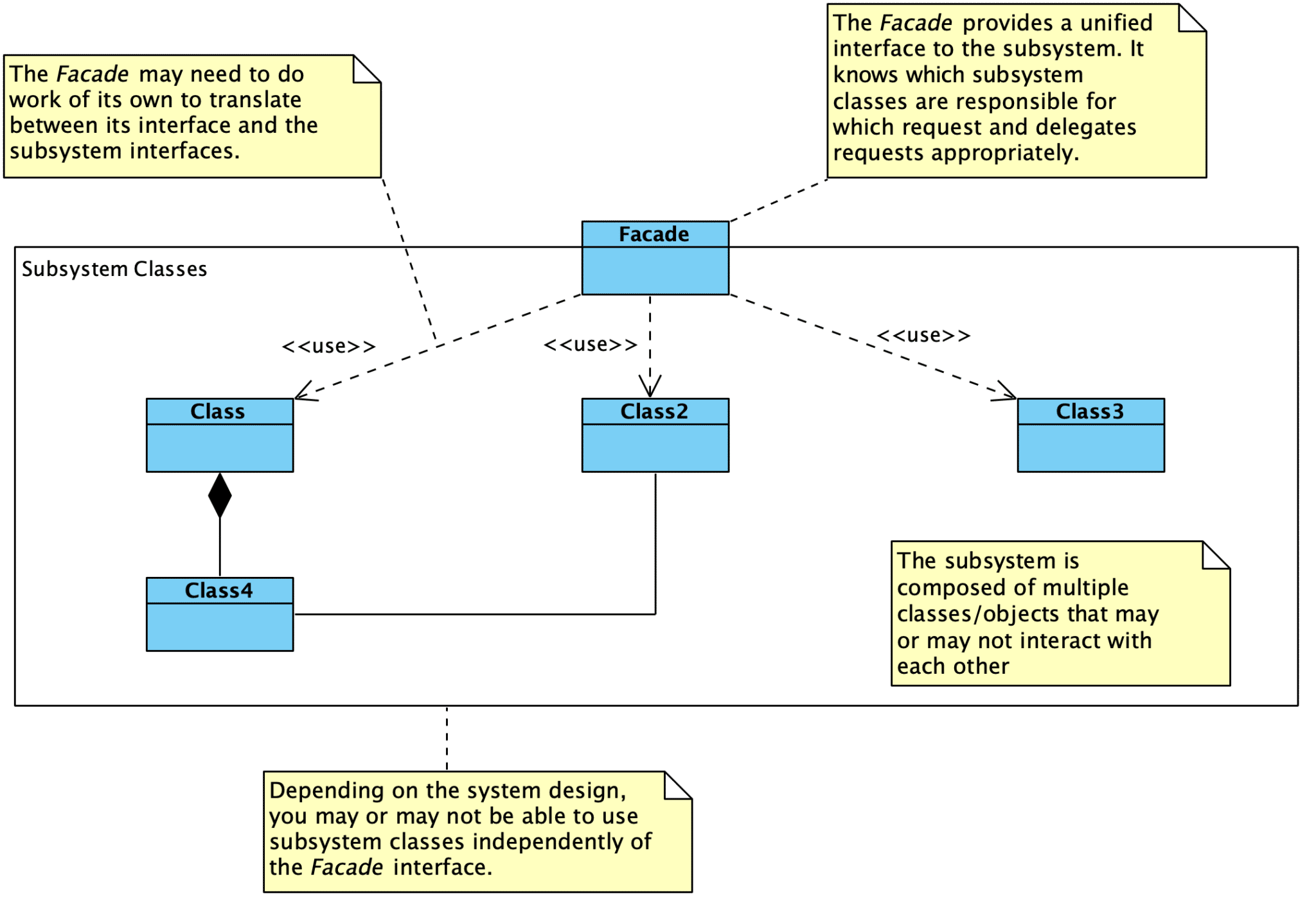
The goal of the Facade pattern is abstracting multiple modules into a single (and often simplified) subsystem interface. Users interact with the subsystem by sending requests to the Facade, which performs any necessary translations and forwards the request to the appropriate subsystem module or class. We might also create an abstract Facade interface that supports multiple implementations. In this case, users would remain decoupled from the Facade implementation by using the abstract interface to communicate with the subsystem.
This approach has four primary benefits:
- We are better able to reason about a single subsystem as a whole than we are able to reason about multiple interacting objects.
- We can simplify the use of a complex subsystem by providing a single simplified interface to users.
- We promote weak coupling between a subsystem and its users by shielding users from the subsystem components.
- Subsystem components might be strongly coupled together, but users are only coupled to the Facade. The subsystem components can be changed without impacting client code.
- We can layer our systems by creating Facades.
Note that a Facade acts as a simplified interface but doesn’t prevent applications from using subsystem modules directly if needed. This approach provides flexibility: the majority of needs can be met by using the simplified Facade interface, while a small subset of complex interactions may require direct use of a subsystem module. When using the Facade for dependency management, you may decide to prevent direct access to subsystem classes to ensure that clients only depend on the Facade.
Differentiating the Patterns
When we think about these two patterns alongside each other, they may seem quite similar. Fundamentally, both patterns are about managing interactions between modules.
The primary difference is in the type of interaction between modules.
Facade abstracts a subsystem to provide a more convenient interface or to shield users from directly interfacing with subsystem modules. The interaction flows in one direction: users make a request of the Facade, and the Facade makes requests of the subsystem modules. In fact, subsystem modules do not know about the existence of the Facade!
The Mediator pattern primarily enables cooperative behavior while keeping modules decoupled. The Mediator pattern allows us to centralize coordination activities that do not belong in the individual modules. Unlike the Facade pattern, Colleagues are aware of the existence of the Mediator and communicate with the mediator instead of directly with each other. The Mediator itself communicates with Colleagues to fulfill requests.
In practice, the lines between these two patterns can blur. Sometimes I can create clearly defined Facades and Mediators. In other cases, I find that the resulting design is a blend of the two patterns.
For example, consider a Facade for a power subsystem. The Facade provides a general interface for handling power-related activities, and it uses the subsystem objects to fulfill the requests.
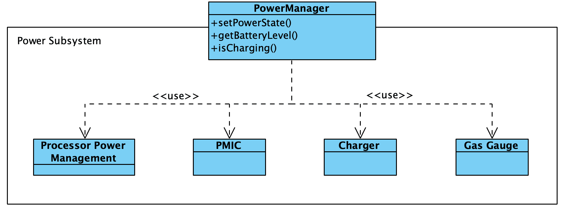
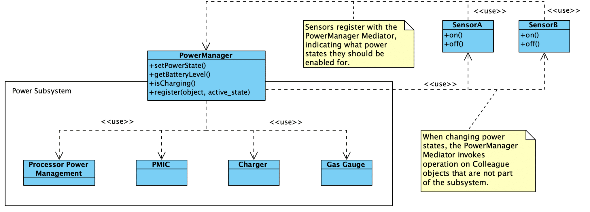
However, we might need a more complex power management module. What if the setPowerState() function interacted with other drivers to control when they are turned on and off? And what if drivers themselves can trigger power state changes through the power management module in response to specific events?
In this case, we end up with something that resembles a blend between the two patterns rather than a pure Facade.
Applicability for Embedded Projects
Both patterns described above are suitable for embedded projects. The most obvious application is delineating our system into subsystems through the use of Facades, such as with the power management facade example shown in the previous section. Rather than working directly with subsystem components, our application code can work with Facades that provide an abstracted interface for working with the subsystem(s). We can change the subsystem details without impacting our application code.
Depending on the design, a hardware abstraction layer (HAL) or board support package (BSP) can also be examples of the Facade and Mediator patterns. Fundamentally, the goal of a HAL or BSP is to provide Facade that higher software layers can use to interact with the underlying hardware. If the components managed by the HAL or BSP can also use the provided interfaces, we end up with a Mediator.
Embedded Artistry’s Approach
In our own standard embedded program design, we create three core Facade/Mediator layers with different responsibilities: Processor, HardwarePlatform, and Platform. We will be exploring each of these concepts in greater detail in the subsequent articles in this series.
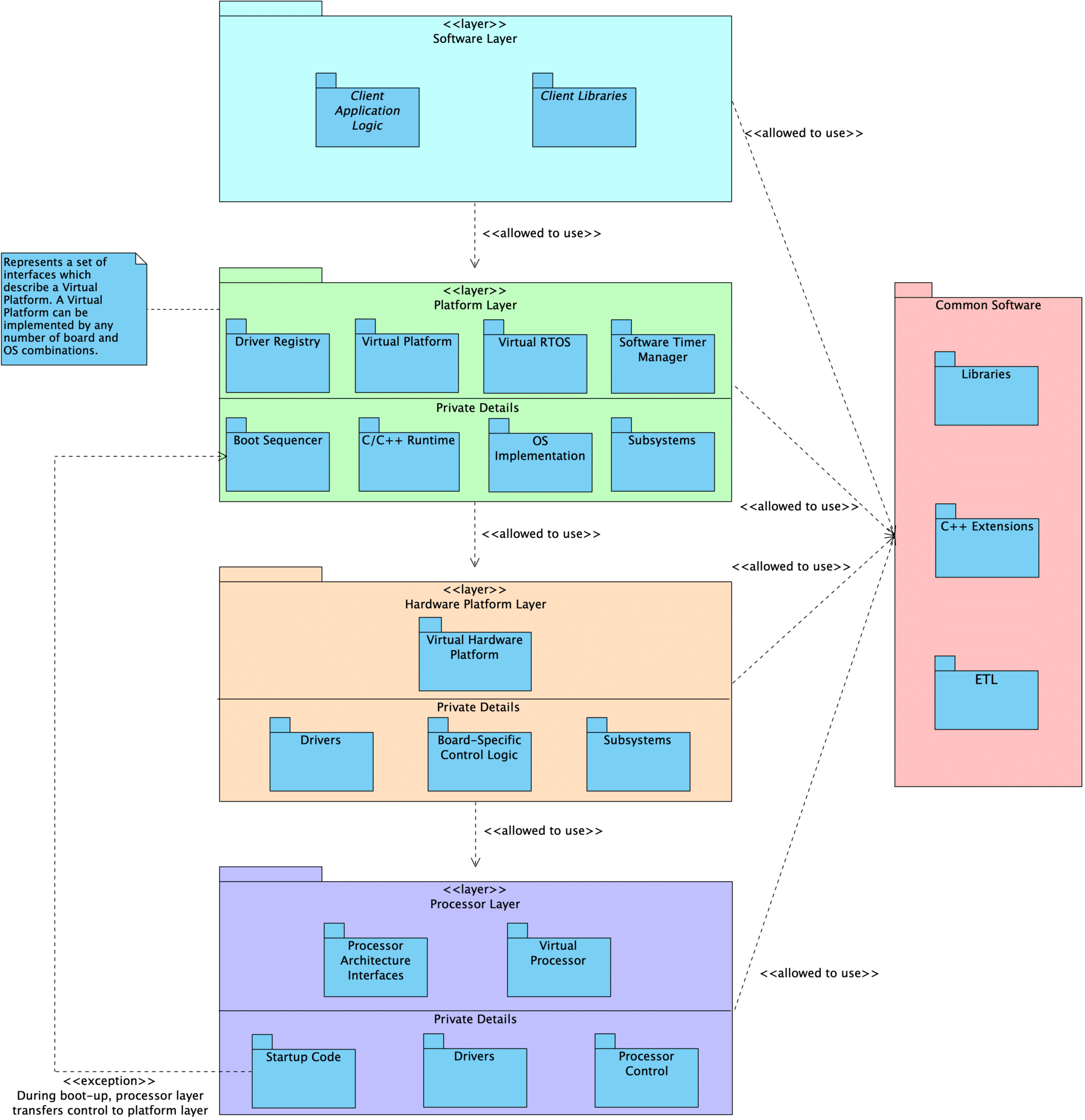
Processor
At the core of an embedded program is the Processor layer. This layer includes the processor peripheral drivers and processor control module. Every processor is unique in its makeup of peripherals, capabilities, and the interfaces we provide. However, we also define an abstract Facade interface that can be used to interact with the Processor as a whole subsystem. This Facade provides APIs such as init() and reset(). Code that interacts with the abstract Facade interface never needs to be updated when we change from one processor to another.
Note: The processor is the biggest source of coupling in embedded programs and presents the most difficulty when we are required to migrate from one processor to another. Ultimately, we don’t want our application layer to know anything about the processor itself.
Hardware Platform
Above the Processor sits a HardwarePlatform, which serves as a Facade/Mediator for the complete hardware subsystem. Responsibilities include:
- Declaration of the system’s
Processorand the necessary peripheral drivers - Declaration of drivers for external peripheral components
- Configuration for the processor peripherals and external peripherals for the application’s needs
- E.g., configure
SPI0to useDMA1, time-of-flight sensor is connected toI2C0on board revision A andI2C1on revision B
- E.g., configure
- Providing standard interfaces used to interact with the underlying hardware at a broad level
- E.g., change power state, reset the board, set the LEDs to indicate an error
Users interact with the hardware using the HardwarePlatform Facade interfaces rather than directly talking to the specific hardware components. Hardware subsystem components (such as i2c1 or tof0) can also be accessed by the rest of the program. Inside of the HardwarePlatform layer, we know the exact types and configuration details for the underlying modules. We can call all of the available interfaces provided by each unique processor and driver type. However, outside of the HardwarePlatform, users are restricted to generic driver interfaces (e.g., i2cMaster instead of nRF52I2CMaster or aardvarkI2CMaster).
In this way, the coupling between drivers and processor peripherals is contained in a single location rather than spread throughout the code base. Client code is only weakly coupled to the underlying hardware through the use of generic driver interfaces and the HardwarePlatform facade interfaces. When we change our processor or an external peripheral, we only need to update the HardwarePlatform.
Platform
The next layer up is the Platform layer. We can imagine that a Platform is the sum of the underlying HardwarePlatform, the chosen operating system (or lack of one), the language standard library, and other supporting constructs. Similar to the HardwarePlatform, we use the Platform as a Facade/Mediator by providing a standard abstract interface. Application logic can only use the interfaces provided by the Platform layer, as well as generic driver interfaces for hardware installed on the board. In this way, the application logic is prevented from being tightly coupled to the specific hardware and platform details. We are free to run our application on any Platform that fulfills its requirements.
Note: For information on how we use our build systems to enforce the layering described above, see Leveraging Our Build Systems to Support Portability.
Putting it All Together
The goal of this article is to provide embedded software developers with additional concepts that can be used when designing embedded software. We want to write embedded programs in a way that enables us to reuse modules across projects, as well as to minimize the amount of rework needed whenever there is a change to the underlying hardware. The design patterns described above are two conceptual tools that we rely on for achieving these goals.
In the next article in this series, we’ll explore driver abstractions and their value in creating portable software. We will combine the driver abstraction concepts with the design patterns introduced in this article to show how we can create abstractions that decouple our software from the underlying processor and hardware platform details.
Further Reading
- Wikipedia: Mediator Pattern
- Wikipedia: Facade Pattern
- Design Patterns: Elements of Reusable Object-Oriented Software
- Designing Embedded Software for Change course
- Our Embedded Virtual Machine project makes use of these patterns
- Virtual Devices in Embedded Systems Software
- Leveraging Our Build Systems to Support Portability
- Prototyping for Portability: Lightweight Architectural Strategies
- Musings on Tight Coupling Between Firmware and Hardware
- Practical Decoupling Techniques Applied to a C-based Radio Driver
Designing Embedded Software for Change
Are you tired of every hardware or requirements change turning into a large rewrite? Our course teaches you how to design your software to support change. This course explores design principles, strategies, design patterns, and real-world software projects that use the techniques.