21 March 2022 by Phillip Johnston • Last updated 24 March 2022Here is the Markdown template we use for documenting design patterns used in our repositories and on our website. Put a 1-2 line summary description up top. Include a brief classification of this pattern (Structural, Decoupling, etc.) if relevant for your purposes. ## Aliases – List any known aliases for this pattern ## Context It can be helpful to give readers brief context and description of the pattern prior to reading the rest of the pattern document. You can also use this as an “Intent” section. – How does …
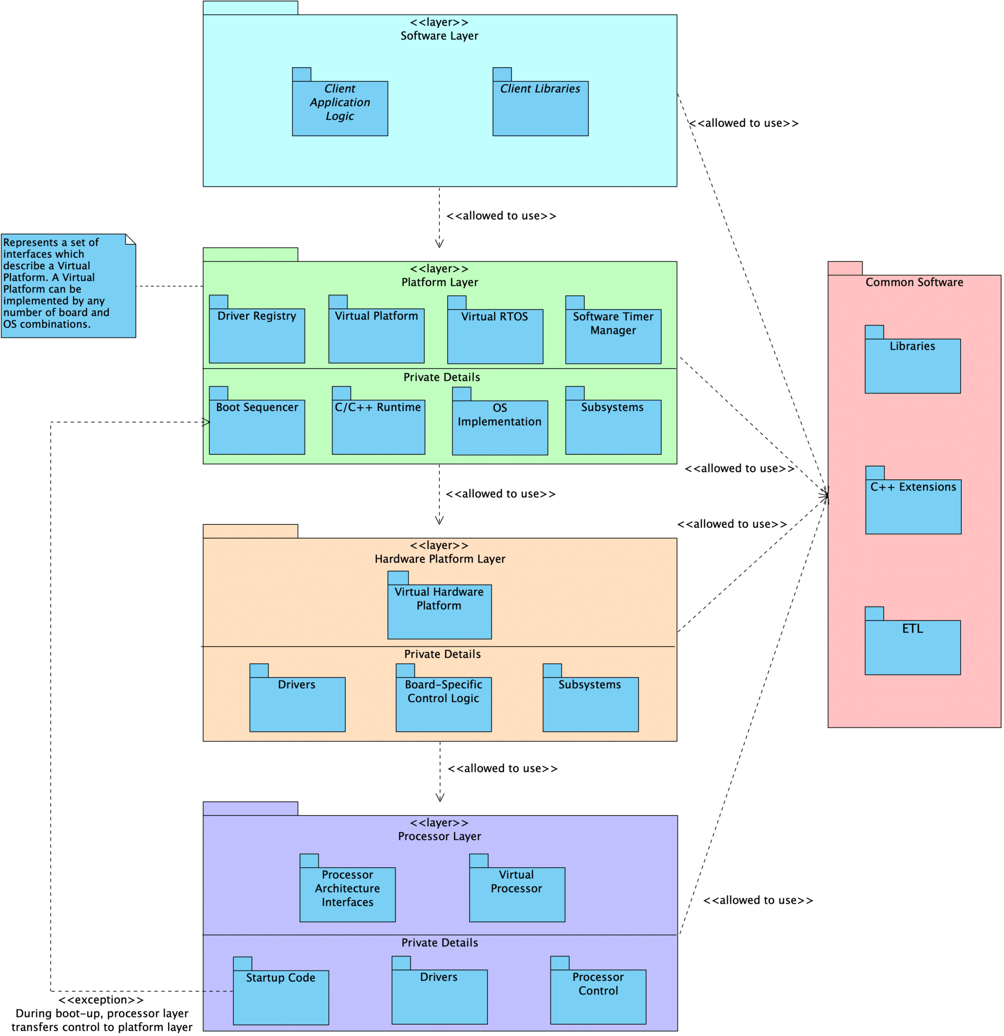
In our standard embedded software design approach, we use a layered architecture that decomposes into four primary layers:
Processor Layer, which abstracts the underlying processor used by the target platform
Hardware Platform Layer, which abstracts the underlying circuit board and provides board-level abstractions for use by the platform layer
Platform Layer, which abstracts the underlying circuit board, operating system, and C/C++ runtime
Software Layer, which sits atop the Platform Layer, which allows it to be portable across platforms (given that requirements are met by the platform implementation)
In addition, there is a cross-cutting Utilities “layer” which is independent of the target platform & architecture. The Utility constructs are usable by all layers.
The primary goal of this layering strategy is to create re-usable and portable device drivers and software constructs for embedded devices and product lines. In order to achieve this goal, the software and hardware segments must be decoupled and interchangeable at the three layering points.
Visual Representation
Layer Description
Processor
At the core of an embedded program is the Processor layer. This layer includes the processor peripheral drivers and processor control module. Every processor is unique in its makeup of peripherals, capabilities, and the interfaces we provide.
We define an abstracted Facade interface that can be used to interact with the Processor as a singular subsystem. This interface provides functionality such as init() and reset(). Code that interacts with the abstract Facade interface never needs to be updated when we change from one processor to another.
Note: The processor is the biggest source of coupling in embedded programs and presents the most difficulty when we are required to migrate from one processor to another. Ultimately, we don’t want our application layer to know anything about the processor itself.
Hardware Platform
Above the Processor sits a HardwarePlatform, which serves as a both a Facade and a Mediator for the complete hardware subsystem.
The responsibilities of this layer include:
Declaration of the system’s Processor and the necessary processor peripheral drivers
Declaration of drivers for external peripheral components
Configuring all peripherals
E.g., configure SPI0 to use DMA1, time-of-flight sensor is connected to I2C0 on board revision A and I2C1 on revision B
Providing standard interfaces used to interact with the underlying hardware at a broad level
E.g., APIs to change power state, reset the board, set the LEDs to indicate an error
User code interacts with the hardware using the HardwarePlatform interfaces rather than directly talking to the specific hardware components.
Hardware subsystem components (such as i2c1 or tof0) can also be accessed by the rest of the program through virtual device interfaces that are common to all components of that category. Inside of the HardwarePlatform layer, we know the exact types and configuration details for the underlying modules. We can call all of the available interfaces provided by each unique processor and driver type. However, outside of the HardwarePlatform, users are restricted to generic driver interfaces (e.g., i2cMaster instead of nRF52I2CMaster or aardvarkI2CMaster).
In this way, the coupling to drivers and processor peripherals is contained in a single location rather than spread throughout the code base. Client code is only weakly coupled to the underlying hardware through the use of the generic virtual device interfaces and the HardwarePlatform Facade interfaces. When we change our processor or select a different external peripheral, we only need to update the HardwarePlatform.
Platform
The next layer up is the Platform layer. We can imagine that a Platform is the sum of the underlying HardwarePlatform, the chosen operating system (or lack of one), the language standard library, and other supporting constructs that our application depends on. Similar to the HardwarePlatform, we use the Platform as a Facade/Mediator by providing a standard abstract interface.
Application logic can only use the interfaces provided by the Platform layer, as well as generic driver interfaces for hardware installed on the board. In this way, the application logic is prevented from being tightly coupled to the specific hardware and platform details. We are free to run our application on any Platform that fulfills its requirements.
Seeing it In Action
This layering scheme is defined in the emvbm-core project. We have example projects built using this strategy:
embvm/blinky contains the application layer code for a simple blinky example. This project runs on a personal computer using an Aardvark adapter hooked up to an LED, an nRF52840 development kit, an nRF USB Dongle, and an STM32 NUCLEO-L4R5ZI development board.
embvm-demo contains a more complicated example application involving LEDs, a time-of-flight sensor, and an OLED display. This application runs on a personal computer using an Aardvark adapter, an nRF52840 development kit, and an STM32L4R5ZI-P Nucleo development kit.
26 August 2021 by Phillip Johnston Last updated 8 December 2021“Use of Abstract Interfaces in the Development of Software for Embedded Computer Systems”, by David Parnas, was published in 1977 and is a precursor to the excellent “A Procedure for Designing Abstract Interfaces for Device Interface Modules” (one of my all-time favorite embedded software papers). I’m working on patterns for managing hardware dependencies in embedded systems software, and I wanted to make sure I included all of the relevantly named papers I can find in my research. Abstract This report describes a procedure for designing computer systems that are developed …
21 June 2021 by Phillip JohnstonIn our summary of Martin Fowler’s article “Is High Quality Software Worth the Cost?”, I described challenges I face when trying to perform up front design or analysis before diving into a new project, no matter how short the proposed effort is. Fowler gives us arguments that we can use for explaining why we think high quality software is worth the investment. Luckily for us, Fowler is in a nice position for this analysis: he’s a proponent of the Extreme Programming (XP) movement, while also being deeply involved in graphical design languages – he wrote …
4 May 2021 by Phillip JohnstonI selected this series from the IT Hare blog as reading club entry: Bringing Architecture of Operating Systems to XXI Century. This series summarizes Sergey’s view of the direction in which we should collectively be headed. While not explicitly about embedded systems, I think there are many ideas that are tied into our field of study. Given that, I wanted to see what insights and lessons we can pull out of this series and apply to our embedded systems work. Given the different directions I’m exploring, such as portability, driver design, and asynchronous programming, I …
The most common challenge we encounter on embedded software projects is the software’s dependency on the hardware. This dependency primarily manifests in embedded software projects in three ways: A belief that firmware development cannot begin in earnest until hardware is available The tendency to use the interfaces provided by an SDK throughout our programs Referencing …
The central theme in our Practical Architecture series is exploring ways that we can design our systems to reduce the costs of change. We've worked with many teams who are asked to change the processor or RTOS, only to realize that their entire program must be rewritten because SDK functions are used throughout the code …
In Leveraging Our Build Systems to Support Portability, I described techniques we can use for enforcing the use of proper abstractions in our embedded programs. By using these techniques, we place ourselves in a better position to respond to changes in the underlying hardware. Components can be quickly swapped out, and code changes are only …
We received a pair of questions that prompted this Q&A article. The first is straightforward: What type of documentation do you create for your code? Do you use UML? Subset of UML? Something else? Can you provide samples? The second question arose during a discussion on Timeless Laws of Software Development, by Jerry Fitzpatrick: The author …
5 June 2020 by Phillip Johnston • Last updated 16 August 2024 “Designing Software for Ease of Extension and Contraction” is a classic paper by David L. Parnas which was published in the IEEE Transactions on Software Engineering in 1979. Designing software to be extensible and easily contracted is discussed as a special case of design for change. A number of ways that extension and contraction problems manifest themselves in current software are explained. Four steps in the design of software that is more flexible are then discussed. The most critical step is the design of a software structure called …