
We received a pair of questions that prompted this Q&A article. The first is straightforward:
What type of documentation do you create for your code? Do you use UML? Subset of UML? Something else? Can you provide samples?
The second question arose during a discussion on Timeless Laws of Software Development, by Jerry Fitzpatrick:
The author admonishes developers to create and record a software architecture for their project before they start coding, and then says “Beware: activity diagrams, flowcharts, and sequence diagrams describe operation, not architecture.” In “Better Embedded Systems Software”, Phillip Koopman says that “an architecture is some figure that had boxes and arrows representing components and connections” and provides examples like “call graph, class diagram, data flow diagram, hardware allocation diagram, control hierarchy diagram” as well as a few exceptions to the rule (“message dictionary, real time schedule, memory map”).
These definitions seem to contradict. What do you consider to be a valid architecture diagram? What are some that you have discovered you prefer over others?
Given that both questions center around diagrams, we’ll focus our answer on that topic. We’ll also share other ways we document our software projects.
Table of Contents:
- Architecture & Design Documentation
- Source Documentation
- Project Documentation
- Source Control Commit Messages
- More for Members
- Further Reading
Architecture & Design Documentation
The architecture and design (A&D) documentation included in a project depends on the complexity of that project and the amount of design effort we applied to it. For this section, we’re going to share the documentation included in one of our more complex projects, since it provides a comprehensive overview.
We tend to separate our A&D documentation into the following categories:
- Component specifications (often called “CRC-R cards”), which describe the responsibilities, requirements, collaborators, and rationale behind a given component.
- Constraints, which document hard constraints that our system must meet. Like component specifications, constraint documentation includes a rational. We also document the source of the constraint, metrics for the constraint (if applicable), and ways to check the constraint (if applicable).
- Qualities, which document the architecture or design qualities that we are designing our system around. Quality documentation includes a description, context, scenarios, test cases, metrics (if applicable), tradeoff notes, and related qualities.
- Principles underlying the design and implementation strategy for the system. Principle documentation includes a description, the rationale, the implications for the project, the counterforces pushing back against the principle, counterarguments to the principle, and the scope at which the principle applies.
- Design Patterns, which contain architecture or code patterns used on the project. Pattern documentation includes a description, context, problem statement, solution, consequences, known use cases, variants, and diagrams.
- Use cases, which contain a written description of how the system will be used. Use case documentation includes a list of actors, pre-conditions, post-conditions, assumptions, steps, variations, related qualities and constraints, and related use cases.
- Visual models (discussed below)
- Architecture decision records (discussed below)
I adopted this documentation approach after taking a Bredemeyer Consulting software architecture workshop and reading the book Documenting Software Architectures.
Note: Want to learn more about architecture & design? Check out the entry in the Embedded Systems Field Atlas.
Visual Modeling
For visually modeling our systems, we primarily use “UML-lite”, augmented by SysML and concepts lifted from the MARTE profile, which focuses on real-time embedded systems. UML and SysML provide a standardized language for visual modeling, which can be helpful for sharing diagrams in external contexts. We call our usage “UML-lite” because we do not make full use of the standard or available constructs, we only use the minimal concepts needed to communicate an idea.
Note: An alternative to UML is the C4 model, produced by Simon Brown. C4 focuses on four different contexts when creating your diagrams.
We use a variety of visual models for our projects. As Fred Brooks outlines in “No Silver Bullet”, software is too complex to be laid out in a convenient 2D geometric representation. We cannot even fully visualize or understand software in a single view of any kind. Ultimately, we need multiple views to understand a system.
Unlike the quote that opened this article, we don’t take a strict stance on what is considered an architectural diagram and what isn’t. For our projects, you will often find a combination of:
- Architectural views:
- Layered views (DSA, using UML class diagrams)
- Conceptual view (DSA, using UML class diagrams)
- System structural view (MARTE, using SysML block diagram)
- Software structural view (MARTE, using SysML block diagram)
- Feature model (SysML block diagram)
- Class diagrams (UML)
- Block diagrams (SysML)
- Communication diagrams (UML/SysML)
- Sequence diagrams (UML/SysML)
- Activity Diagrams (UML)
- State charts (UML)
- Use Case Diagrams (UML)
Our goal is to create models that help us design and understand our system. We do not create detailed models of every aspect of the system. We focus our modeling efforts on areas of high risk, high potential for change, high conceptual difficulty, or critical importance to the success of the project. We also use our models when evaluating whether our project is likely to meet design qualities, principles, and constraints.
State machines are one area where we combine visual modeling with code generation. Two well-built tools are:
- QM, which produces code for the Quantum Leaps QP framework
- Yakindu Statechart Tools, which produces platform-agnostic state machine code
If you want to learn more about visual modeling and documenting the design of a program, we recommend the following books:
Example Visual Models
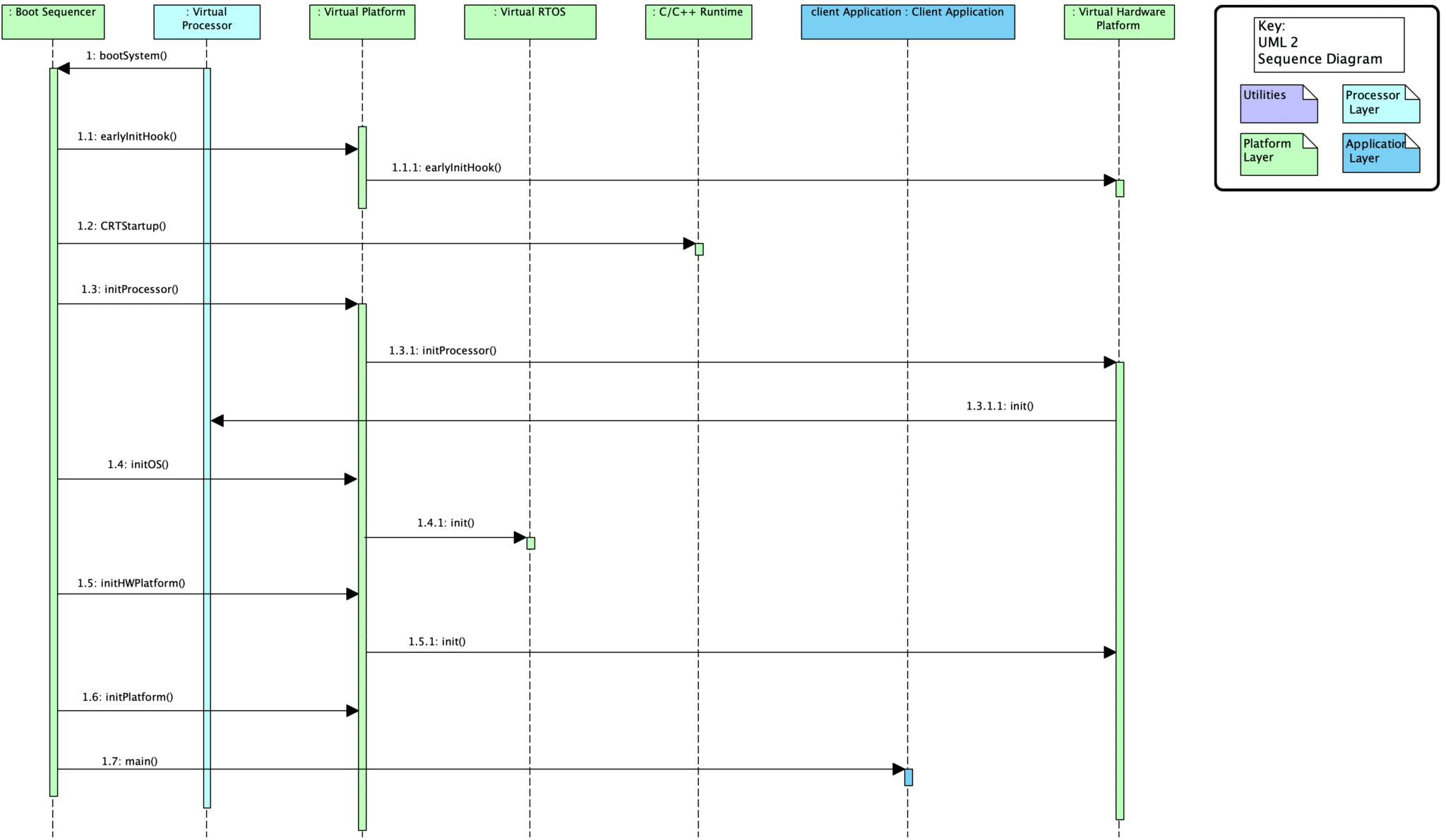
This UML sequence diagram for our C++ embedded framework shows the interactions between different system components during the boot process.
This UML statechart corresponds to our asynchronous dispatch queue.

Sometimes the diagrams are more exploratory in nature. For example, I sketched this UML class diagram while I was thinking about a common driver interface for communication busses. It was never fleshed out beyond this. I didn’t need any further detail to push my ideas forward.

Here’s another lightweight UML diagram. This activity diagram captures an incomplete model of the startup flow for an OS X program. Many details are left out, but it captures the essential ideas and serves as a valuable anchor. In this diagram, green blocks represent programs, and purple blocks represent libraries.

A UML communication diagram was used to model the startup process for an nRF52 board using Newlib.

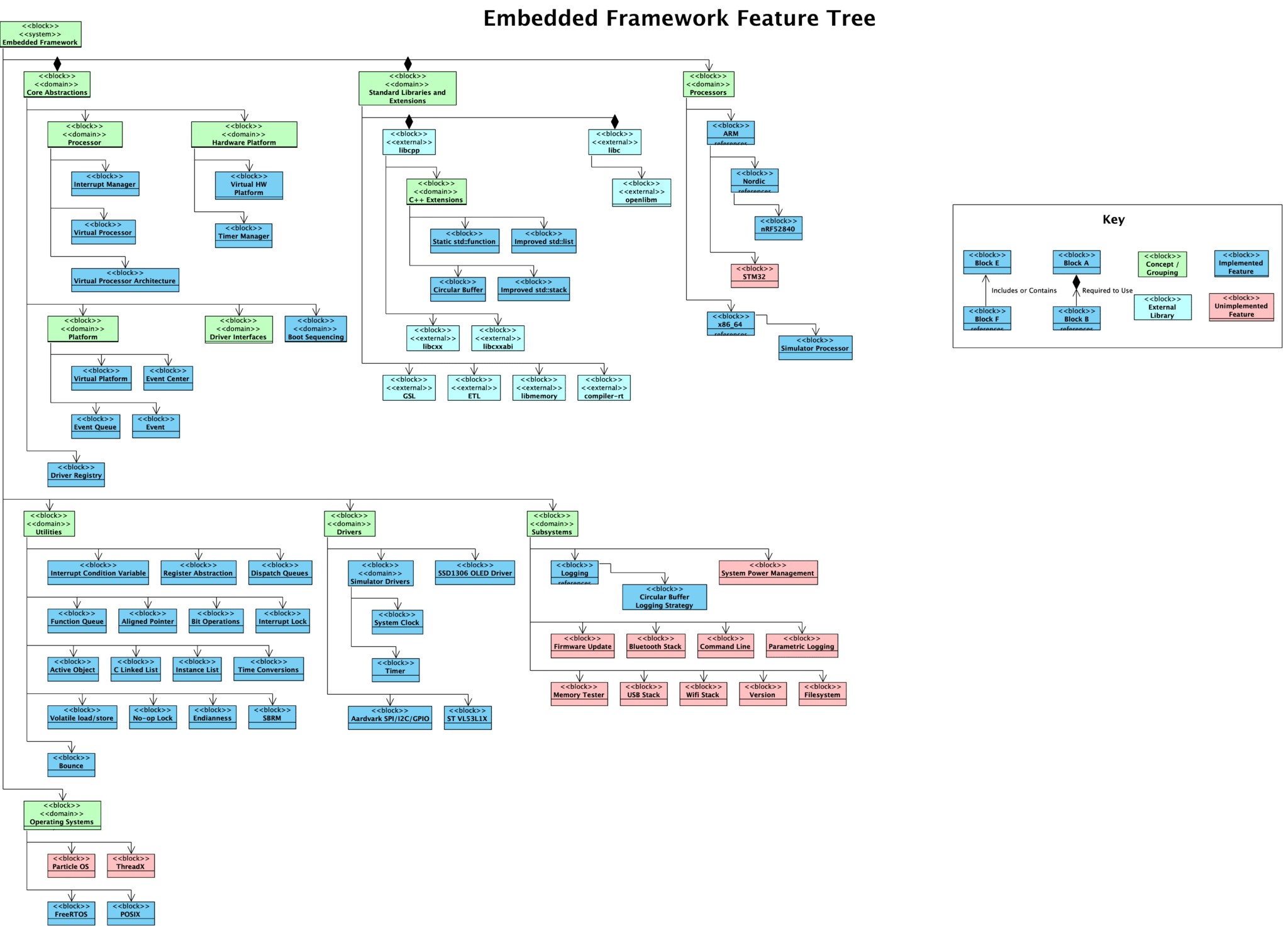
Sometimes we leverage standard diagram types for non-standard purposes. For example, a SysML block diagram was used to create a “feature tree” for our embedded framework. This diagram represents how framework features are hierarchically organized, which differs from how the classes interact and how the files are organized.
Architecture Decision Records
We use npryce/adr-tools to document significant architectural decisions within our repositories as “architecture decision records” (ADRs).
adr list
docs/architecture/decisions/0001-record-architecture-decisions.md
docs/architecture/decisions/0002-layering-scheme.md
docs/architecture/decisions/0003-no-dynamic-memory-allocation-in-core.md
docs/architecture/decisions/0004-track-documentation-alongside-source.md
docs/architecture/decisions/0005-provide-non-blocking-interfaces.md
docs/architecture/decisions/0006-differentiate-drivers-and-hal.md
docs/architecture/decisions/0007-differentiate-between-processor-implementation-and-architecture.md
docs/architecture/decisions/0008-virtual-platform-as-mediator-pattern.md
docs/architecture/decisions/0009-event-driven-framework-design.md
These records allow us to record significant decisions that have a significant impact on the development of the program, allowing future developers to understand the context behind past decisions. Each record contains a status, the background context, the decision that was made, and consequences of that decision.
# 3. No Dynamic Memory Allocation in Core

Date: 2018-07-06

## Status

Accepted

## Context

Many systems, teams, and designs require that the system will not utilize dynamic memory allocation. We should maintain a flexible design by allowing users to use dynamic memory allocation if they desire. However, we should be able to support the strictest operating model for maximum flexibility and potential use of the framework.

## Decision

No dynamic memory allocation will be utilized by framework core components

## Consequences

* Framework remains open for use by teams who will not allow dynamic memory allocation
* Constructs which are provided by C/C++ but require dynamic memory allocation will need to be re-written with a static option (e.g., static_function, static_queue)
ADRs can be related to each other, and they can supersede previous decisions. The tool can generate a dependency graph showing how different decisions are related, which can be included in the source documentation.
Source Documentation
We use Doxygen for documenting our source code. We do our best to document all public function prototypes and all custom types. We focus our efforts on expected use of function arguments, return values, pre-conditions, post-conditions, and any potential side effects.
We typically configure Doxygen to generate dependency graphs for each file, allowing us to see how a single module relates to other modules.
Project Documentation
There’s more to project documentation than the design and the code:
How to Use the Project
Developers often forget to document the most important part: how people are supposed to use the software!
At a minimum, this information is kept in the project’s README. Most projects grow in complexity, so we keep basic instructions in the README and provide additional information in separate documents.
pottery
We use npryce/pottery on our projects to make notes about events that occur in the “real world”. This might be change in direction, funding, customer gain/loss, developers joining/leaving the team, etc. The goal is to provide additional context to a repository that helps future developers understand the evolution of a project.
pottery show
2020-05-07T21:11:19Z

Yesterday, I refactored the build system to match the design I created in one of our online courses. I also updated the build system module and deleted many of the custom tooling scripts. This is an effort toward standardizing the builds for all of our projects.
Software Inventory
We keep a spreadsheet in our repositories (stored using git-lfs) that tracks external projects. We reference the path to the project, the current version (if relevant), the license used by that project, and the path to the license file.
This inventory helps us whenever we need to get legal input on a project, since all of the external project information is documented in a single location.
Security and Safety Plans
If our organizations maintain security plans and/or safety plans, we like to keep these tracked within the relevant project repositories. This allows us to track changes to the plans as needed, and also ensure that the plans are easily referenced by the developers.
Developer Guides
Whenever necessary, we include “developer guides” in our project documentation. We consider a developer guide anything that helps developers work on a project. This can be setup instructions for a development environment, instructions for deploying a new build, information about the error model used by the system, or the coding standard for the project.
Source Control Commit Messages
Don’t forget that your source control commit messages also help you document your projects! Commit messages can be written such that they provide context to the changes that are made in that commit, helping developers understand how and why the system evolved in the way it did.
More for Members
Our members have access to additional resources and recommendations in the Embedded Systems Field Atlas:
- Architecture & Design provides recommendations for learning more about designing software
- Visual Modeling provides links to tools, standards, and references for visually modeling software
- Documentation provides links and recommendations for documenting your projects
- Safety Plan provides information about creating a safety plan for your safety-critical system
- Security Plan provides information about creating a security plan for your product
- Source Control Commit Guidelines help to ensure that your source control commits also serve as useful project documentation
- Design Pattern Catalogue contains an ever-expanding collection of patterns that can be used on your projects
- Paper: No Silver Bullet discusses the complex nature of software, explaining why we need so much information
Further Reading
- Documenting Architectural Decisions Within our Repositories
- Your Project is Great, So Let’s Make Your README Great Too
- npryce/pottery
- npryce/adr-tools
If you want to learn more about visual modeling and documenting the design of a program, we recommend the following books: