
In our standard embedded software design approach, we use a layered architecture that decomposes into four primary layers:
- Processor Layer, which abstracts the underlying processor used by the target platform
- Hardware Platform Layer, which abstracts the underlying circuit board and provides board-level abstractions for use by the platform layer
- Platform Layer, which abstracts the underlying circuit board, operating system, and C/C++ runtime
- Software Layer, which sits atop the Platform Layer, which allows it to be portable across platforms (given that requirements are met by the platform implementation)
In addition, there is a cross-cutting Utilities “layer” which is independent of the target platform & architecture. The Utility constructs are usable by all layers.
The primary goal of this layering strategy is to create re-usable and portable device drivers and software constructs for embedded devices and product lines. In order to achieve this goal, the software and hardware segments must be decoupled and interchangeable at the three layering points.
Visual Representation
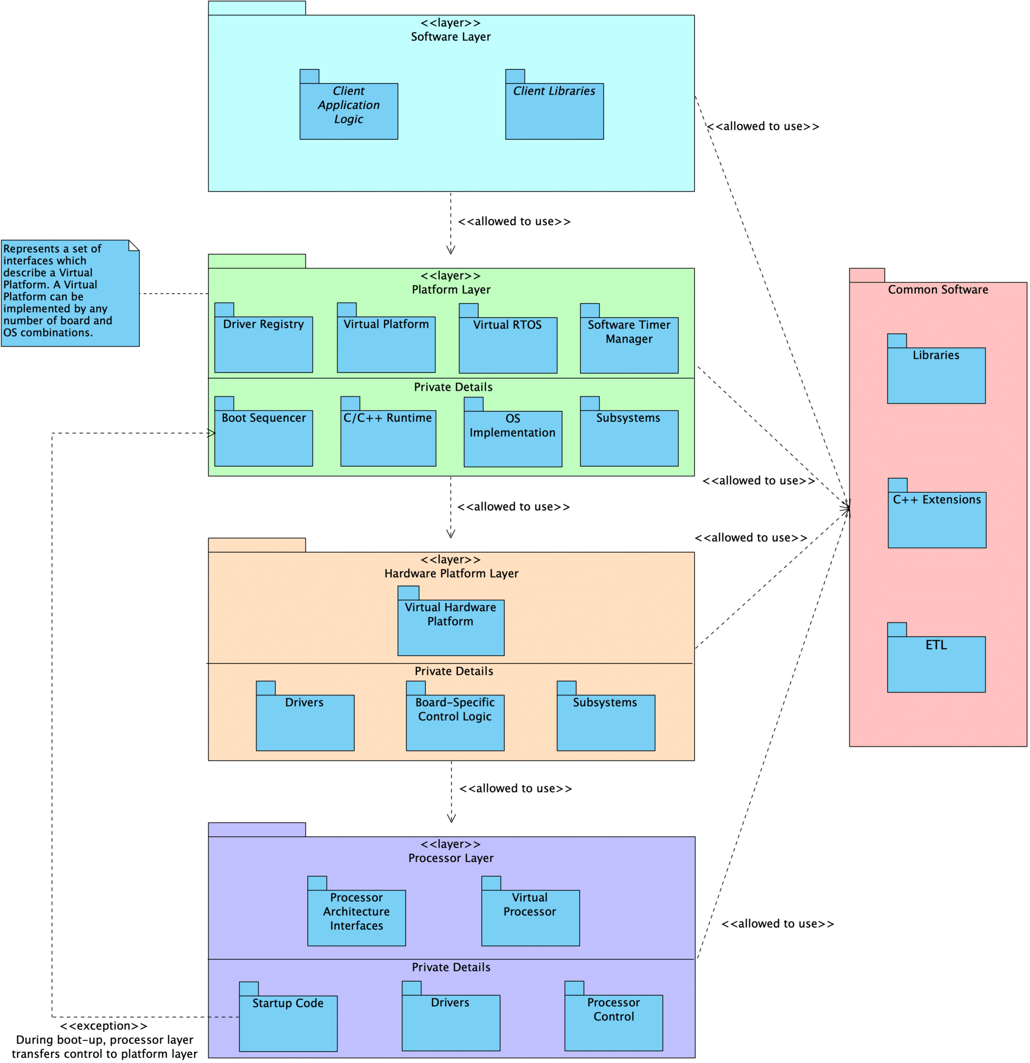
Layer Description
Processor
At the core of an embedded program is the Processor layer. This layer includes the processor peripheral drivers and processor control module. Every processor is unique in its makeup of peripherals, capabilities, and the interfaces we provide.
We define an abstracted Facade interface that can be used to interact with the Processor as a singular subsystem. This interface provides functionality such as init() and reset(). Code that interacts with the abstract Facade interface never needs to be updated when we change from one processor to another.
Note: The processor is the biggest source of coupling in embedded programs and presents the most difficulty when we are required to migrate from one processor to another. Ultimately, we don’t want our application layer to know anything about the processor itself.
Hardware Platform
Above the Processor sits a HardwarePlatform, which serves as a both a Facade and a Mediator for the complete hardware subsystem.
The responsibilities of this layer include:
- Declaration of the system’s
Processorand the necessary processor peripheral drivers - Declaration of drivers for external peripheral components
- Configuring all peripherals
- E.g., configure
SPI0to useDMA1, time-of-flight sensor is connected toI2C0on board revision A andI2C1on revision B
- E.g., configure
- Providing standard interfaces used to interact with the underlying hardware at a broad level
- E.g., APIs to change power state, reset the board, set the LEDs to indicate an error
User code interacts with the hardware using the HardwarePlatform interfaces rather than directly talking to the specific hardware components.
Hardware subsystem components (such as i2c1 or tof0) can also be accessed by the rest of the program through virtual device interfaces that are common to all components of that category. Inside of the HardwarePlatform layer, we know the exact types and configuration details for the underlying modules. We can call all of the available interfaces provided by each unique processor and driver type. However, outside of the HardwarePlatform, users are restricted to generic driver interfaces (e.g., i2cMaster instead of nRF52I2CMaster or aardvarkI2CMaster).
In this way, the coupling to drivers and processor peripherals is contained in a single location rather than spread throughout the code base. Client code is only weakly coupled to the underlying hardware through the use of the generic virtual device interfaces and the HardwarePlatform Facade interfaces. When we change our processor or select a different external peripheral, we only need to update the HardwarePlatform.
Platform
The next layer up is the Platform layer. We can imagine that a Platform is the sum of the underlying HardwarePlatform, the chosen operating system (or lack of one), the language standard library, and other supporting constructs that our application depends on. Similar to the HardwarePlatform, we use the Platform as a Facade/Mediator by providing a standard abstract interface.
Application logic can only use the interfaces provided by the Platform layer, as well as generic driver interfaces for hardware installed on the board. In this way, the application logic is prevented from being tightly coupled to the specific hardware and platform details. We are free to run our application on any Platform that fulfills its requirements.
Seeing it In Action
This layering scheme is defined in the emvbm-core project. We have example projects built using this strategy:
- embvm/blinky contains the application layer code for a simple
blinkyexample. This project runs on a personal computer using an Aardvark adapter hooked up to an LED, an nRF52840 development kit, an nRF USB Dongle, and an STM32 NUCLEO-L4R5ZI development board. - embvm-demo contains a more complicated example application involving LEDs, a time-of-flight sensor, and an OLED display. This application runs on a personal computer using an Aardvark adapter, an nRF52840 development kit, and an STM32L4R5ZI-P Nucleo development kit.
- embvm-demo-patforms contains example platforms and hardware platforms that are shared by our blinky and embvm-demoprojects
- stm32l4 provides an example hardware platform, platform, and blinky application that will run on an STM32 NUCLEO-L4R5ZI development kit.
References
- embvm-core Documentation: Architectural Layer View describes this layering scheme in much more detail, with explanations given to each element
- For information on how we use our build systems to enforce the layering described above, see Leveraging Our Build Systems to Support Portability
- Managing Coupling with the Mediator and Facade Patterns presents this information in the context of the design patterns that inspired this scheme
- Virtual Devices in Embedded Systems Software