Abstraction Layer

An “Abstraction Layer” is a set of abstractions that together form a boundary between different conceptual levels in a system. Code above the boundary interacts only with the abstractions the layer exposes; code below the boundary contains the implementations. Neither side needs to know the details of the other. Abstraction layers are commonly used to isolate hardware-specific code from application logic, to separate protocol handling from transport details, to decouple an OS from the drivers it manages, or to abstract subsystems. Simple abstraction layers may look no different from an Abstract Interface, while complex abstraction layers may provide several interfaces that can be relied upon.

The key property of a well-designed abstraction layer is that the lower layers can be swapped (different hardware, a different OS, a different transport layer, or a different subsystem) without requiring changes to the layers above.

C++26

C++26 is the informal name for the standard following C++23. A full list of changes along with implementation status can be found on cppreference.

Exploring the Changes

C++ trainer Rainer Grimm has published a series of articles covering changes in the new standard version:

Using C++26 Capabilities

Rainer Grimm has published a series on implementing a lock-free stack using new C++26 capabilities:

References

Strategy Pattern

The Strategy pattern separates the interface of an algorithm, operation, or behavior from the implementation, allowing implementations to become interchangeable. The implementation can then be varied independently from the client code that uses the interface.

Table of Contents:

  1. Aliases
  2. Context
  3. Forces
  4. Solution
  5. Consequences
  6. Known Uses
    1. Examples
  7. Implementation Variations
  8. Related Patterns
  9. References
Note

For simplicity’s sake, we use the word “algorithm” below to stand in for “algorithm, operation, or behavior.” These terms are equivalent in the Strategy pattern context.

Aliases

  • Algorithm Object

Context

Systems can be broken down into components with distinct purposes. For example, you can find operations that create or read data, that operate on the data, and that output the data somewhere else.

Sometimes, a single implementation for an operation will suffice. In other cases, the system would benefit from being able to support multiple implementations. For example:

  • New hardware revisions may have hardware-enabled capabilities that previous revisions did not (e.g., a cryptographic co-processor, additional memory)
  • Different data streams may benefit from different compression algorithms
  • Users may desire different output formats
  • Filtering methods may vary depending on the situation

Different algorithm implementations will be appropriate at different times. Sometimes, you will need to support run-time selection, and other times compile-time. Sometimes, the user of an algorithm will require an implementation that you didn’t think of, and will benefit from being able to add their own.

You need some way to separate the implementation of the algorithm from the code that uses the algorithm. It is difficult to add new implementations and change existing ones if they are integral (i.e., tightly coupled) to the client code.

How can you structure your system to support algorithm selection and extension with minimal overhead and rework?

Forces

This pattern attempts to balance the following forces:

Solution

The basic principle behind the Strategy pattern is to decouple the algorithm use from the implementation(s) of the algorithm. With the Strategy pattern, a component forwards or delegates some aspect of its behavior to a separate Strategy component. The behavior can be changed by selecting the desired Strategy implementation.

By decoupling the algorithm implementation from the code that uses the algorithm, you can enable users to customize the implementation without requiring changes to the code that interacts with the algorithm.

You can implement the Strategy pattern through this process:

  1. Identify an algorithm that needs to be configurable or varied (or might need to be configured in the future)
  2. Define a standard interface for the algorithm
    • This should be an interface that supports all possible desirable implementations of the algorithm
  3. Couple client code to the standard interface rather than a specific implementation
  4. Create implementations of the algorithm interface
  5. Provide a mechanism for selecting the desired algorithm

Conceptually, the structure of the pattern is:


Strategy is an abstract interface with one or more concrete implementations. The client code interacts with the abstract strategy interface, rather than with a specific implementation.

Client code only knows about the algorithm abstraction, not the particular implementation. This allows any suitable implementation of the abstraction to work with the client code.

Successfully implementing the strategy pattern requires that the Strategy interface is sufficiently well defined and general enough to support desired implementations. Interface stability is critical. You should not have to change the Strategy interface or the client code to support a new algorithm.

Consequences

Benefits of the pattern include:

  • The implementation of an algorithm is decoupled from the code that interacts with that operation, allowing them to change independently.
  • Strategies provide different implementations of the same behavior, allowing users to select or create implementations with the desired performance/memory tradeoffs.
  • The design reflects a better Separation of Concerns: use of the algorithm is separated from implementation of the algorithm.
  • The design enables use of the Open-Closed Principle, since implementations can be added or extended without requiring changes to code that interacts with the core algorithm interface.

Tradeoffs include:

  • Changes to the Strategy interface will propagate not only to the caller but also to every implementation of the Strategy. Up-front effort must be invested in getting this interface right.
  • Strategy implementations must be discoverable by users, and they must have enough context/documentation for users to evaluate them.
  • Strategy adds a layer of indirection. While suitable for most cases, there are some cases where tighter coupling will be beneficial.
  • To support a wide range of implementations, the Strategy interface must support sufficient data exchange. It is likely that some implementations will not require all the provided data, resulting in data/space overhead. If this is a measured problem, tighter coupling might be warranted.

Known Uses

  • The primary use of the Strategy pattern is to support different variants for an algorithm. These might represent different space/time tradeoffs or simply different approaches.
    • Design Patterns: Elements of Reusable Object Oriented Software provides the following examples:
      • Using the Strategy pattern for a text compositing algorithm, where you might have a SimpleLayoutStrategy and a TeXLayoutStrategy.
      • A compiler might use the Strategy pattern to allow different register allocation schemes for different target machines.
  • If you have several similar classes or modules that differ only in behavior, you can use the Strategy pattern to reduce duplication. A core structure can be created, with variable behavior handled as separate Strategy implementations. The desired behavior configured by selecting the appropriate implementation.
  • The Strategy pattern provides an alternative to having many conditional statements for controlling behavior. You can encapsulate the conditioned behaviors in a Strategy. Behavior is then controlled by selecting the desired implementation, allowing you to eliminate the conditional branching.
  • Strategy can hide the details of the algorithm implementation (e.g., a complex, implementation-specific data structure) in adherence to the principle of Information Hiding.
  • Library and framework authors can use the Strategy pattern to allow users to override default implementations,. This way, users can to fine-tune the library as needed..
  • Even if you don’t need to change algorithms or operations at run-time, being able to adjust implementations during the development process while mitigating changes in other components.

Examples

  • The C++ standard library frequently uses the Strategy pattern (often via “Policies” supplied via template parameters). Some examples include:
  • Locking can be easily implemented as a Strategy, allowing users to customize locking behavior for the system (e.g., use the RTOS mutex, disable interrupts). You could also disable locking by providing an implementation that does nothing.
    • C++ has a BasicLockable requirement, for example, which allows the use of any type that provides lock and unlock methods.
  • The Embedded Artistry Arduino Logging Library (GitHub) uses the Strategy pattern by providing a standard logging interface along with several logger implementations. The implementation can be changed while allowing the logger clients to remain unchanged.
  • Practical Decoupling Techniques Applied to a C-based Radio Driver shows a use of the Strategy pattern to decouple the driver from the underlying SPI communication bus implementation.
  • Payments are useful to handle in a Strategy-based approach (one which can be selected by users at runtime). Different users wish (or need) to use different payment processors, while the applications’s need to process a payment is fixed.
  • In Making Embedded Systems: Design Patterns for Great Software, Elecia White uses an example of processing ADC data.

    Let’s go back to the data-driven system in Figure 6-2, where analog data is digitized by an ADC, attenuated by the processor, and then sent back to analog via the DAC. What if you weren’t sure you wanted to attenuate the signal? What if you wanted to invert it? Or amplify the signal? Or add another signal to it?

    You could use a state machine, but it would be a little clunky. Once on every processing pass, the code would have to check which algorithm to use based on the state variable.

    Another way to implement this is to have a pointer to a function (or object) that processes data. You’ll need to define the function interface so every data-processing function takes the same arguments and returns the same data type. But if you can do that, you can change the pointer on command, thereby changing how your whole system works (or possibly how a small part of your system modifies the data).

  • Some examples from a discussion in the community forum:
    • Strategy for radio scheduling algorithms
    • Battery charging strategies and protocols
    • For a product that provides a UI of a magnetic sensor and LED, define a strategy interface that allows the UI to be customized per product (e.g., some interact by swiping the magnet, others by attaching/removing the magnet).
  • The following pieces of software analyzed in the Designing Embedded Software for Change course make use of the Strategy pattern to decouple the driver control code from the communication bus read and write operations:

Implementation Variations

The core idea of the Strategy pattern is to define an interface for an algorithm and decouple from the specific algorithm used to allow ease of variation. This can be applied in several ways.

The canonical approach has the Strategy pattern implemented through an (abstract) base class interface with one or more derived implementations. A function pointer or other Callable type (or struct of several Callables) works just as well and is often a superior way to handle small Strategy interfaces.

The binding time of the pattern can also vary. The canonical presentation of the Strategy pattern uses virtual inheritance, which allows for changing the desired strategy at run-time. You can also control which implementation is used at compile-time (hard-coding, C++ templates, C++ concepts, Rust traits, preprocessor conditionals, etc.) or link time (e.g., selectively compiling and linking in the desired implementation for an interface).

Futher reading

Policy-Based Design and the Curiously Recurring Template Pattern (CRTP) in C++ are often described as a compile-time implementation of the Strategy pattern.

You could also view Strategy methods/objects similarly to “optional steps” in the Template Method Pattern. If there’s a defined Strategy (e.g., a valid pointer to a Strategy object), the caller will use it normally. If one isn’t supplied, a default behavior is carried out instead. This can simplify the situation for users, as they do not have to bother with defining a Strategy at all unless the default behavior is insufficient.

You might also implement an optional strategy by defaulting to a “Null Strategy” implementation (or “Null Object”), which does nothing. For example, a locking/exclusion strategy might provide a NullLock implementation that does nothing, allowing locking to be disabled.A common example in this category is providing a NullLock implementation for a locking strategy. If locking is not needed, the NullLock can be used. Otherwise, users could select from a MutexLock, InterruptLock, etc.

Another considerable source of variation is how data is exchanged with the Strategy implementation:

  • Data can be passed in as parameters to the Strategy operations (“take the data”)
  • A context/reference (e.g., to the calling code) is passed as an argument, and the Strategy implementation can request data as needed.
  • The Strategy implementation can request data from another source (e.g., a central data store)
  • The Strategy Pattern can be viewed a larger-scale extension of the ideas behind the Template Method Pattern: Strategy varies an algorithm or operation in its entirety, where Template Method is used to vary individual steps of an algorithm while enforcing an overall algorithm structure.
    • Others distinguish these two patterns by saying that Template Method uses inheritance while Strategy uses delegation (delegating the algorithm to another section of code). We find this distinction as artificially limiting, since the idea behind Template Method can be applied even without inheritance and can also be viewed as delegation.
  • The State pattern is like the Strategy pattern in structure and implementation, but the intent of the pattern is different (encapsulate state-dependent behavior vs encapsulate an algorithm).
  • The Null Object or Nullable pattern is often used with the Strategy pattern.

References

  • Design Patterns: Elements of Reusable Object-Oriented Software by Gamma et al.

    The key to applying the Strategy pattern is designing interfaces for the strategy and its context that are general enough to support a range of algorithms.

  • Making Embedded Systems: Design Patterns for Great Software, 2nd edition, by Elecia White

    Sometimes it isn’t the data that needs to be selected, depending on the situation. Instead, sometimes the path of your code needs to change based on the environment.

    Some embedded systems are too constrained to be able to change the algorithm on the fly. However, you probably still want to use the strategy pattern concepts to switch algorithms during development. The strategy pattern helps you separate data from code and enforces a relatively strict interface to different algorithms.

  • Real-Time Software Design for Embedded Systems by Hassan Gomaa

    An algorithm object encapsulates an algorithm used in the problem domain. This kind of object is more prevalent in real-time, scientific, and engineering domains. Algorithm objects are used when there is a substantial algorithm used in the problem domain that can change independently of the other objects. Simple algorithms are usually operations of an entity object, which operate on the data encapsulated in the entity object. However, in many scientific and engineering domains, complex algorithms need to be encapsulated in separate objects because they are frequently improved independently of the data they manipulate, for example, to improve performance or accuracy.

  • The Strategy Pattern – MC++ BLOG

  • How to model the strategy pattern in Rust? – Stack Overflow

Proto Stage [Proto]

The Proto stage in the NPI Process involves creating prototype devices and finalizing the product design. Prototypes are tested and evaluated to ensure they meet the requirements and specifications as outlined in Product Requirements Specification. During this stage, there will often be several adjustments and modifications to the design.

The Proto stage often involves creating a small number of units (1-10). Only rarely will complete units be built – and if they are, they are often non-enclosed devices (NEDs), wire-wrapped prototypes, or systems assembled out of existing off-the-shelf development kits. Mechanical components are often quickly prototyped, such as with a 3D printer. “Looks-like” prototypes may be created, but lack any actual functionality, while the “works-like” prototypes are often too large to fit into the target enclosure at this stage.

There is often little-to-no testing that happens at the Proto stage. If there are tests, they are usually for informational purposes only, and not for preventing units from leaving the line.

NPI Process Flow

  • The Proto stage begins once there is a Product Requirements Specification and engineering resources are assigned.
  • The Proto stage is completed once there is enough confidence in the design specifications and approach.
  • After the Proto stage is complete, EVT begins.

References

  • NPI Process
  • Hardware engineers speak in code: EVT, DVT, PVT decoded – Instrumental by Anna-Katrina Shedletsky

    The Proto build is a small test run of key product concepts to gain confidence that they can work — potentially a combination of different form factors including looks-like and works-like.

    Purpose: to understand risks around specific modules or designs, usually with multiple variants in low quantities, such as:

    • Fragility of coverglass in drop test with different adhesives, perhaps done on dummy housing bucks
    • Waterproofness of five different button seal designs

    Typical Quantities: 10 or fewer, sometimes no “full systems” are even built

    • Parts may be “stand-ins” or rapidly prototyped (which may change results for better or worse)
    • Sub-modules do not have to be integrated — units may be “works like” or “looks like”

    Things that Go Wrong:

    • Part quality is poor, resulting in incorrect dimensions or an interference was missed in the CAD (3D model), so parts do not fit together and have to be modified by hand
    • Pin 1s on connectors were not correctly mapped, so things do not electrically work even when plugged together
    • The intended design fails miserably during testing and needs to be redesigned

    Exit Criteria: one design concept for the product that the team has reasonable confidence is three major iterations or less from a mass-production worthy design

Python

Python is a widely used general-purpose scripting language.

Table of Contents:

  1. Resources
  2. On Embedded Artistry

Resources

  1. Learning Python
  2. Advanced
  3. Style Guides
  4. Quality Enforcement

Learning Python

Advanced

Style Guides

Quality Enforcement

  • Linters are tools for finding potential bugs and style problems in Python source code. They find problems that are typically caught by a compiler for less dynamic languages like C and C++.
  • Black is a Python formatter
  • Type Checking
    • Mypy is a static type checker for Python that aims to add compile-time type checking with no runtime overhead.

On Embedded Artistry

Open-Closed Principle [OCP]

The Open-Closed Principle (OCP) is a software design principle that states:

Software entities (classes, modules, functions, etc.) should be open for extension, but closed for modification.

The OCP can be restated in more familiar terms, such as in Patterns in the Machine: A Software Engineering Guide to Embedded Development:

The Open-Closed Principle (OCP) says that you want to design your software so that if you add new features or some new functionality, you only add new code; you do not rewrite existing code. A traditional example of the OCP is to introduce an abstract interface to decouple a “client” from the “server.”

We prefer an even more generalized form of the OCP: design your software components so that you can add new functionality or customize behavior without changing the source code of the component.

Note

The OCP is the “O” in the SOLID acronym.

Table of Contents:

  1. Evolution of the OCP
  2. Applying the OCP
  3. Benefits
  4. Balancing Points
  5. Examples
  6. Related Concepts
  7. References

Evolution of the OCP

Bertrand Meyer is the originator of the OCP, and he described it as follows:

A module will be said to be open if it is still available for extension. For example, it should be possible to add fields to the data structures it contains, or new elements to the set of functions it performs.

A module will be said to be closed if [it] is available for use by other modules. This assumes that the module has been given a well-defined, stable description (the interface in the sense of information hiding).

A class is closed, since it may be compiled, stored in a library, baselined, and used by client classes. But it is also open, since any new class may use it as parent, adding new features. When a descendant class is defined, there is no need to change the original or to disturb its clients.

What Meyer described is essentially what we would describe as “implementation inheritance”. Nowadays, the idea of implementation inheritance has fallen out of favor. As a result, some people look negatively at the OCP based on this interpretation of it.

Robert Martin took the idea of the OCP and refocused it on abstract interfaces and polymorphism.

In contrast to Meyer’s usage, this definition advocates inheritance from abstract base classes. Interface specifications can be reused through inheritance but implementation need not be. The existing interface is closed to modifications and new implementations must, at a minimum, implement that interface.

[…]

the implementations can be changed and multiple implementations could be created and polymorphically substituted for each other.

This restatement, focused on abstract interfaces that are closed to change, sounds quite like David Parnas’s information hiding principle. Martin himself notes that “on a module level, this idea is best applied in conjunction with information hiding”.

Martin also provided a helpful restatement of what it means to be “open” and “closed”:

Modules that conform to the open-closed principle have two primary attributes.

  1. They are “Open For Extension”.
    This means that the behavior of the module can be extended. That we can make the module behave in new and different ways as the requirements of the application change, or to meet the needs of new applications.
  2. They are “Closed for Modification”.
    The source code of such a module is inviolate. No one is allowed to make source code changes to it.

More recently, we (and others) generalize the idea even further. The authors of Patterns in the Machine: A Software Engineering Guide to Embedded Development provide the following restatement:

Adding new functionality should not be done by editing existing source code. That is the frame of mind you need to approach designing every module with, and you achieve it by putting together a loosely coupled design.

Our own restatement of the OCP advises us to design your software components so that you can add new functionality or customize behavior without changing the source code of the component..

These two contemporary restatements of the OCP get to the heart of the matter: prevent changes from cascading throughout a system by a) putting up firewalls, b) making components “closed” to specific changes, and c) providing mechanisms to externally extend and control behaviors without modifying a component’s source code.

Applying the OCP

The OCP advises us that software components should be open for extension yet closed for modification. On the surface, this appears to be a conundrum: the typical way one would extend the behavior of a component is by changing it! If a component cannot be changed, how can it be extended?

This question can be attacked from multiple angles:

  1. Abstract Interfaces
  2. Providing Hooks for External Customization
  3. Implementation Decisions

Ensuring a component adheres to the OCP is an explicit design decision. Designers must choose what types of extensions and changes that a component is closed against (or whether the OCP applies to a component at all). Mechanisms must be provided by the component to support the target extensions. To provide actual benefit, the existence of these extension mechanisms is not enough – they must be documented so they can be used effectively to achieve the goals of the OCP. It is also wise to document what changes a component is/isn’t closed against for future maintainers.

Abstract Interfaces

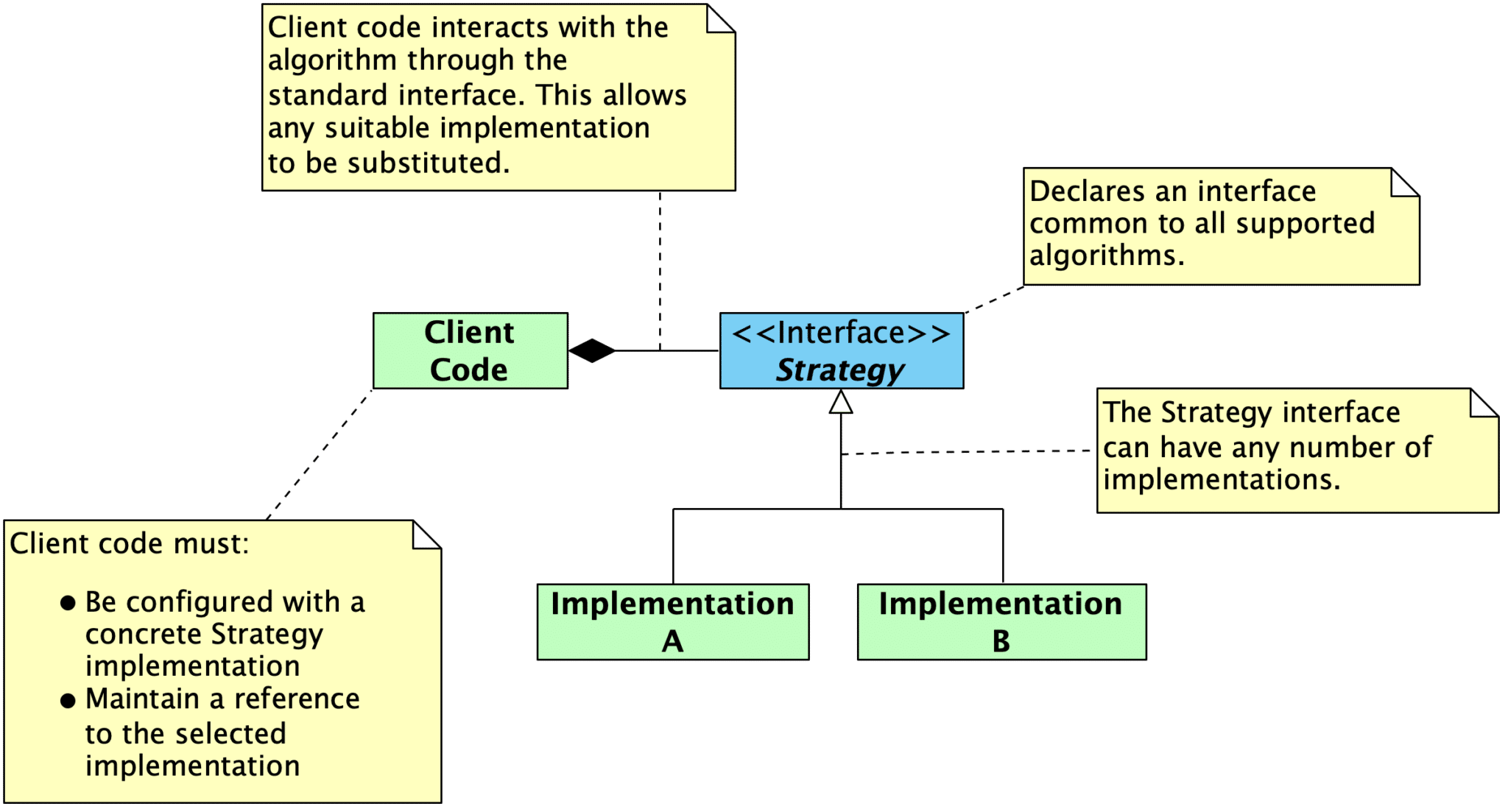
The classical answer to resolving these two competing goals is abstraction. In general, this is a broad answer, since abstraction takes many forms. Martin’s OCP largely focuses on abstract interfaces combined with dynamic polymorphism (i.e., inheritance) or static polymorphism (e.g., templated parameters in C++ that expect a particular interface).

In C++, using the principles of object oriented design, it is possible to create abstractions that are fixed and yet represent an unbounded group of possible behaviors. The abstractions are abstract base classes, and the unbounded group of possible behaviors is represented by all the possible derivative classes. It is possible for a module to manipulate an abstraction. Such a module can be closed for modification since it depends upon an abstraction that is fixed. Yet the behavior of that module can be extended by creating new derivatives of the abstraction.

Abstract interfaces can be viewed as “specifications”, and these specifications can be reused through inheritance even though the implementation is not. The interface specifications will be closed to modifications. New implementations that satisfy the interface can be created, leaving the implementation of the interface open to extension. New behaviors and requirements are implemented by providing new implementations rather than by modifying existing implementations, since those are closed to modifications. In this sense, the OCP can be viewed simply as a restatement of the information hiding principle, and all of the associated advice will apply equally well here.

Further reading

For more on abstract interfaces, see:

Providing Hooks for External Customization

Abstract interfaces are a useful tool for achieving the goals of the OCP, but they are not the only tool. Here are techniques that enable your software components to be configured and extended by user applications:

  1. Configuration Parameters
  2. Template Method Pattern
  3. Callbacks
  4. Communicating Through Queues
  5. Table-Driven Behavioral Specifications

Configuration Parameters

One of the easiest ways to achieve the OCP is to provide configuration options for your software component. This way, user applications can control the behavior of your component without changing the component’s source code. You can supply configuration options in several ways:

  • Run-time configuration options, such as specifying desired values in a struct that is passed into a component through a constructor or initialization routine

  • C++ template parameters for classes and function

  • Using the preprocessor and #ifndef to provide compile-time configuration using a build system, a dedicated configuration system like KConfig, or a configuration header.

    #ifndef SCREEN_WIDTH_PX
    #error You must provide a definition for SCREEN_WIDTH_PX. 
    #endif
    
    #ifndef SCREEN_HEIGHT_PX
    #error You must provide a definition for SCREEN_HEIGHT_PX. 
    #endif
    
    #ifndef PIXELS_PER_BYTE
    #define PIXELS_PER_BYTE 8 
    #endif
    
    #ifndef SCREEN_BUFFER_SIZE_BYTES
    // Calculated: (width in px * height in px) / pixels per byte
    #define SCREEN_BUFFER_SIZE_BYTES ((SCREEN_WIDTH_PX * SCREEN_HEIGHT_PX) / PIXELS_PER_BYTE)
    #endif 
    

The more parameters that can be controlled from outside of your software component, the better. This reduces the likelihood that you will need to change the component in the future.

Template Method Pattern

The Template Method pattern can provide users with the ability to customize actions taken by your component. You can designate template methods that comprise one or more optional or required steps. These steps can be supplied or overridden by user programs, enabling user applications to change aspects of your component’s behavior without modifying the component source code.

Template methods are useful in the following scenarios:

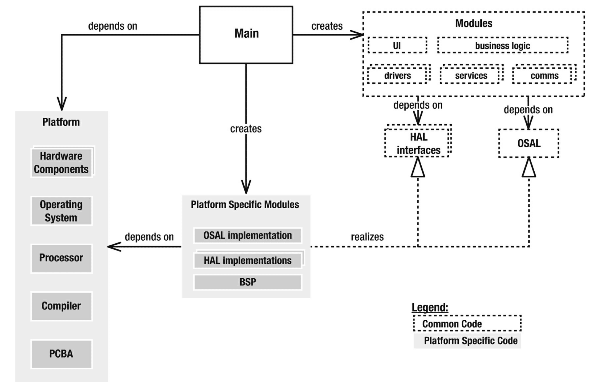
  • Decoupling a component from platform-specific details. The application can specify those based on its target platform. This enables the component to work with any platform that can implement the required step(s).
  • Decoupling one component from another. Instead, a template method can be supplied, allowing an external component to connect the components together.
  • Allowing users to configure, extend, or override a componet’s behavior to meet their application’s requirements.

Callbacks

Similar to the Template Method pattern, callback functions provide user applications with customization points that can extend a component’s behavior without modifying its source code. Callback functions are typically invoked when a particular action occurs (e.g., transfer complete callback, error callback). User applications can implement callback handlers in order to connect components together from the outside or to take an application-specific action in response to the event.

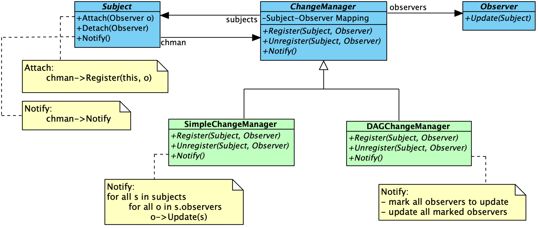
The Observer Pattern can be used in the same way as a callback function. This pattern is useful when there are multiple subscribers who may be interested in an event.

Communicating Through Queues

Rather than communicating through interfaces, components can instead communicate through queues. The data format (closed to modification) passed through the queue becomes the primary interface. Producers and consumers of information can be swapped out without the need to modify the component(s) on the other end.

Communication through queues can also be combined with other mechanisms, such as template methods or callbacks. This combination can prevent your component from becoming coupled to a specific queue implementation. It also gives your users the flexibility to decide whether or not a queue should be used at all.

Table-Driven Behavioral Specifications

Some aspects of a component that are likely to change over time can be defined in a table, and the application will be made responsible for supplying the table implementation. The component itself can then become agnostic to the contents, simply understanding how to generically access the information present in the table for its purposes. Changes can be handled through the application’s definition of the table, leaving the source code of component itself unchanged. Tables are also useful for specifying application-specific configuration details.

Further reading

For more information, see:

Encapsulation

The OCP also depends on proper encapsulation. Within the OCP context, you should be particularly concerned about properly encapsulating implementation details so that they cannot be accessed or modified directly – components should only interact through the published interfaces. This means applying the following two design policies in your system:

  1. Eliminate Global Variables
  2. Make Member Variables Private

Eliminate Global Variables

Martin states this more strongly: “No global variables – ever”. He points out that the use of global variables makes the OCP impossible to achieve:

The argument against global variables is like the argument against public member variables. No module that depends upon a global variable can be closed against any other module that might write to that variable. Any module that uses the variable in a way that the other modules don’t expect will break those other modules. It is too risky to have many modules be subject to the whim of one badly behaved one.

Make Member Variables Private

Similar to the advice to eliminate global variables, all class member variables and “file global” member variables in a component should be made private so they cannot be accessed from outside of the component.

In OOD, we expect that the methods of a class are not closed to changes in the member variables of that class. However we do expect that any other class, including sub- classes are closed against changes to those variables. We have a name for this expectation, we call it: encapsulation.
– Robert Martin

Benefits

The OCP is an essential tool in designing software for change. Intentionally designing your software components to be easily extended and closed to change improves the ability of your systems to respond to change.

In the strictest sense, you are designing components that a) never change and b) are implemented against an abstract interface. Changes in requirements will then mean that you are going to a) create a new extension to existing behavior, or b) create a new component to implement the new requirements for the existing interface(s). In either case, you will not change old code to get your desired behavior.

Components that adhere to the OCP act as a “firewall” against change. Because you are adding new code instead of modifying existing code (and working through abstract interfaces), changes are prevented from cascading throughout a system. They are isolated to the creation of a new component and its integration into the system.

Quote

All systems change during their life cycles. This must be borne in mind when developing systems expected to last longer than the first version.
– Ivar Jacobson

Balancing Points

The OCP is best viewed as a goal or a guiding light. Software components cannot be 100% closed against all extensions or changes. Some changes will affect “closed” components by their nature. For example:

  • The methods of a class or component are not closed to changes in the private variables of that component, but external components interfacing with that component are closed to changes in the private variables.
  • Components are not closed to interface changes. They will cascade into all components that use the interface.
  • Components are not closed to changes resulting from discovering an implementation error, design error, or error in understanding.

Examples

The following examples show how different techniques can be used (and combined) to achieve the OCP in production code.

  • The AX5043 driver uses a template method to allow applications to configure the driver’s SPI interactions without modifying the driver source code. Several configuration parameters are also provided through “instance structures”, allowing applications to configure the radio for the intended use case. Multiple radio instances can be supported with the use of multiple instance structures.
  • embeddedartistry/libc provides common implementations for standard library functions and headers, while deferring architecture-specific implementation details to architecture-specific headers. New processor architectures can be supported by creating a new architecture-specific tree, defining the types appropriately for that platform, and supplying additional function implementations as needed. The base headers and function implementations require no modifications.
  • embeddedartistry/libmemory provides a single, common memory allocation interface (i.e., malloc and friends) with multiple implementations to the interface that can be selected by users. New allocation schemes are added by creating new implementations. This library also uses the template method pattern to enable user applications to externally specify locking behavior for thread safety without modifying the implementation source.
  • The embeddedartistry/printf library provides a template method that applications can use to configure the output for the printf family of functions (putchar_()), as well as multiple compile-time configuration options that can tune the library for a specific application and platform.
  • The Embedded Virtual Machine framework heavily uses the OCP by applying many of the techniques discussed above: abstract interfaces with multiple implementations, template methods, configuration options, and callbacks.
  • The Patterns in the Machine repository was designed with the OCP in mind. Using the OCP is also discussed in the corresponding book.

References

  • Information Hiding

  • Wikipedia: Open-Closed Principle

  • Wikipedia: SOLID

    The open–closed principle: “Software entities … should be open for extension, but closed for modification.”

  • Object Oriented Software Construction by Bertrand Meyer

    A class is closed, since it may be compiled, stored in a library, baselined, and used by client classes. But it is also open, since any new class may use it as parent, adding new features. When a descendant class is defined, there is no need to change the original or to disturb its clients.

  • Design Principles and Design Patterns by Robert Martin

    A module should be open for extension but closed for modification.

    Of all the principles of object oriented design, this is the most important. It originated from the work of Bertrand Meyer It means simply this: We should write our modules so that they can be extended, without requiring them to be modified. In other words, we want to be able to change what the modules do, without changing the source code of the modules.

    This may sound contradictory, but there are several techniques for achieving the OCP on a large scale. All of these techniques are based upon abstraction. Abstraction is the key to the OCP. Several of these techniques are described below.

    The techniques Martin mentions to achieve the OCP are dynamic polymorphism (i.e., inheritance from an abstract interface) and static polymorphism (i.e., polymorphism acheived through templates and generics).

    Architectural Goals of the OCP. By using these techniques to conform to the OCP, we can create modules that are extensible, without being changed. This means that, with a little forethought, we can add new features to existing code, without changing the existing code and by only adding new code. This is an ideal that can be difficult to achieve, but you will see it achieved, several times, in the case studies later on in this book.

    Even if the OCP cannot be fully achieved, even partial OCP compliance can make dramatic improvements in the structure of an application. It is always better if changes do not propogate into existing code that already works. If you don’t have to change working code, you aren’t likely to break it.

  • The Open-Closed Principle” by Robert Martin

    As Ivar Jacobson said: “All systems change during their life cycles. This must be borne in mind when developing systems expected to last longer than the first version.” How can we create designs that are stable in the face of change and that will last longer than the first version? Bertrand Meyer gave us guidance as long ago as 1988 when he coined the now famous open-closed principle. To paraphrase him:

    SOFTWARE ENTITIES (CLASSES, MODULES, FUNCTIONS, ETC.) SHOULD BE OPEN FOR EXTENSION, BUT CLOSED FOR MODIFICATION.

    When a single change to a program results in a cascade of changes to dependent modules, that program exhibits the undesirable attributes that we have come to associate with “bad” design. The program becomes fragile, rigid, unpredictable and unreusable. The open- closed principle attacks this in a very straightforward way. It says that you should design modules that never change. When requirements change, you extend the behavior of such modules by adding new code, not by changing old code that already works.

    Modules that conform to the open-closed principle have two primary attributes.

    1. They are “Open For Extension”.
      This means that the behavior of the module can be extended. That we can make the module behave in new and different ways as the requirements of the application change, or to meet the needs of new applications.
    2. They are “Closed for Modification”.
      The source code of such a module is inviolate. No one is allowed to make source code changes to it.

    It would seem that these two attributes are at odds with each other. The normal way to extend the behavior of a module is to make changes to that module. A module that cannot be changed is normally thought to have a fixed behavior. How can these two opposing attributes be resolved?

    Abstraction is the Key.

    In C++, using the principles of object oriented design, it is possible to create abstractions that are fixed and yet represent an unbounded group of possible behaviors. The abstractions are abstract base classes, and the unbounded group of possible behaviors is represented by all the possible derivative classes. It is possible for a module to manipulate an abstraction. Such a module can be closed for modification since it depends upon an abstraction that is fixed. Yet the behavior of that module can be extended by creating new derivatives of the abstraction.

    Since programs that conform to the open-closed principle are changed by adding new code, rather than by changing existing code, they do not experience the cascade of changes exhibited by non-conforming programs.

    It should be clear that no significant program can be 100% closed. […] In general, no matter how “closed” a module is, there will always be some kind of change against which it is not closed.

    Since closure cannot be complete, it must be strategic. That is, the designer must choose the kinds of changes against which to close his design. This takes a certain amount of prescience derived from experience. The experienced designer knows the users and the industry well enough to judge the probability of different kinds of changes. He then makes sure that the open-closed principle is invoked for the most probable changes.

    In OOD, we expect that the methods of a class are not closed to changes in the member variables of that class. However we do expect that any other class, including sub- classes are closed against changes to those variables. We have a name for this expectation, we call it: encapsulation.

    Make all Member Variables Private.

    No Global Variables — Ever.

    The argument against global variables is similar to the argument against pubic member variables. No module that depends upon a global variable can be closed against any other module that might write to that variable. Any module that uses the variable in a way that the other modules don’t expect, will break those other modules. It is too risky to have many modules be subject to the whim of one badly behaved one.

    On the other hand, in cases where a global variable has very few dependents, or cannot be used in an inconsistent way, they do little harm. The designer must assess how much closure is sacrificed to a global and determine if the convenience offered by the global is worth the cost.

    Again, there are issues of style that come into play. The alternatives to using globals are usually very inexpensive. In those cases it is bad style to use a technique that risks even a tiny amount of closure over one that does not carry such a risk. However, there are cases where the convenience of a global is significant. The global variables cout and cin are common examples. In such cases, if the open-closed principle is not violated, then the convenience may be worth the style violation.

    Conformance to this principle is what yeilds the greatest benefits claimed for object oriented technology; i.e. reusability and maintainability. Yet conformance to this principle is not achieved simply by using an object oriented programming language. Rather, it requires a dedication on the part of the designer to apply abstraction to those parts of the program that the designer feels are going to be subject to change.

  • Patterns in the Machine : A Software Engineering Guide to Embedded Development by John Taylor and Wayne Taylor

    The Open-Closed Principle (OCP) says that you want to design your software so that if you add new features or some new functionality, you only add new code; you do not rewrite existing code. A traditional example of the OCP is to introduce an abstract interface to decouple a “client” from the “server.”

    Restatement:

    Adding new functionality should not be done by editing existing source code. That is the frame of mind you need to approach designing every module with, and you achieve it by putting together a loosely coupled design.

    PIM’s interpretation of the OCP, then, is quite literally: Adding new functionality should not be done by editing existing source code. That is the frame of mind you need to approach designing every module with, and you achieve it by putting together a loosely coupled design.

    Strategic (OCP)—Think long term when designing and implementing modules.

    It is also important to recognize that a module cannot be 100% closed against all possible extensions. Furthermore, not every module needs to be OCP friendly. It is the responsibility of the designer, architect, and developer to choose what type of extensions a module is closed against. As with most things in life, good choices come with experience, and a lot of experience comes from bad choices.

  • The Open-Closed Principle. and what hides behind it | HackerNoon.com by Vadim Samokhin

Configuration Table Pattern

Store configuration and initialization information inside of a table, and pass the table to an initialization routine that iterates over the table entries.

Problem

When attempting to create a portable and reusable software design, you need to decouple your application code from the underlying platform – the OS, the hardware, and any other non-portable constructs. Abstraction layers (OSAL, HAL) are typically used to create a decoupling point in the application. You can write drivers and modules that interact only with the provided abstractions, and changes below the abstractions will not require corresponding changes in the application layer.

One challenge in this scheme is handling initialization and configuration. Initialization requirements and available settings vary widely across devices, processors, and OSes. Attempting to create a general abstraction for these settings is a fool’s errand, as you will end up with too many potential options; only a limited set will apply to any given device, rendering the abstraction useless. Hiding this information within the driver or HAL implementation is also risky: each application will need different settings, meaning that you need to change the HAL for each application. How can you properly handle configuration and initialization while still benefiting from abstraction?

A separate problem from the one stated above: configuration and initialization information, such as thread settings and thread creation calls, are often scattered throughout an application. How can you group these settings together in a single, easy-to-find location?

Solution

One way to address this problem is by defining and maintaining configuration tables for each of the various peripheral devices, OS types, and other non-portable constructs. All relevant information required for configuration and initialization is stored in these tables. They are specified at the application level, allowing each application (or the various configurations) to initialize the underlying hardware system according to its needs. Drivers and abstraction layers can remain reusable and do not need to be modified to support different configuration settings.

Specifying configurable settings in this way allows you to maintain a generic interface. There is no need to craft an initialization interface that supports all possible configuration settings. You can create a generic initialization function, such as OS_thread_init(const OS_thread_config_t* config). While the exact definition of the configuration structure may change from one RTOS to another, the initialization interface will remain the same, and the definitions for each RTOS will be consistent across different applications. This achieves a suitable middle ground for designing for change while still supporting implementation-specific configuration options.

Implementation

To implement this pattern, proceed through the following steps:

  1. Identify the Configuration Parameters
  2. Create the Configuration Structure and Supporting Types
  3. Populate the Table
  4. Create the Initialization Routine

Identify the Configuration Parameters

First, you need to identify the common configuration parameters that apply for your processor (family). This information can be found by reviewing the datasheet or the chip vendor drivers. Find what registers exist and what the various fields in the registers mean. Looking at different code examples can also be helpful for figuring out what typical configuration patterns are.

As you review this information, make a list of the various configurable parameters as well as possible values for that parameter..

Note

For the purposes of abstraction, especially if supporting multiple processors in a given family, you should focus primarily on common settings that are available. However, configuration is something that typically varies from one processor to another, so do not be surprised if you need to use different configuration table definitions for different processor families.

For example, here is a common set of configurable parameters for a timer:

  • Timer mode
  • Enabled/disabled status
  • Clock source
  • Clock pre-scaler
  • Count direction (up/down)
  • Target count / interval / period
  • Periodic / one-shot

Here is a common set of configurable parameters for GPIO:

  • Direction (input/output/tri-state)
  • Pull-up/down setting
  • Drive options (normal, hi-drive)

You will also want to determine how the different parameters will be “mapped”. Some drivers will be mapped to a specific instance, such as TIMER0 and TIMER1. Others, like DMA, may have a combination of a “device” (DMA0, DMA1) and “channel” (1..8). GPIO will commonly be mapped to a “port” (GPIOA, GPIOB) and “pin number”

Create the Configuration Structure and Supporting Types

Once you have identified the various parameters and options, you are ready to create a structure that contains all the configurable settings.

Beningo offers the following timer configuration structure example in Reusable Firmware Development:

typedef struct {
	uint32_t TimerChannel; /**< Name of timer */
	uint32_t TimerEnable; /**< Timer Enable State */
	uint32_t TimerMode; /**< Counter Mode Seettings */
	uint32_t ClockSource; /**< Defines the clock source */
	uint32_t ClockMode; /**< Clock Mode */
	uint32_t ISREnable; /**< ISR Enable State */
	uint32_t Interval; /**< Interval in microseconds */
} TimerConfig_t;

While Beningo shows plain uint32_t values above, we prefer to use enumerations or vendor-supplied parameters for configuration table values, making them more readable and easier to reference. For Beningo’s GPIO configuration structure example, he uses this approach:

/**
* Defines the digital input/output configuration table’s elements that are used
* by Dio_Init to configure the Dio peripheral.
*/
typedef struct
{
/* TODO: Add additional members for the MCU peripheral */
	DioChannel_t Channel;          /**< The I/O pin        */
	DioResistor_t Resistor;         /**< ENABLED or DISABLED     */
	DioDirection_t Direction;    /**< OUTPUT or INPUT                */
	DioPinState_t Data;               /**<HIGH or LOW          */
	DioMode_t Function;            /**< Mux Function  - Dio_Peri_Select*/
} DioConfig_t;

Example definitions for the enumerations referenced above are shown below.

/**
* Defines the possible states for a digital output pin.
*/
typedef enum
{
	DIO_LOW,                                  /** Defines digital state ground */
	DIO_HIGH,                                 /** Defines digital state power */
	DIO_PIN_STATE_MAX                        /** Defines the maximum digital state */
} DioPinState_t;

/**
* Defines an enumerated list of all the channels (pins) on the MCU
* device. The last element is used to specify the maximum number of
* enumerated labels.
*/
typedef enum
{
	/* TODO: Populate this list based on available MCU pins */
	FCPU_HB,                   /**< PORT1_0 */
	PORT1_1,                   /**< PORT1_1 */
	PORT1_2,                   /**< PORT1_2 */
	PORT1_3,                   /**< PORT1_3 */
	UHF_SEL,                   /**< PORT1_4 */
	PORT1_5,                   /**< PORT1_5 */
	PORT1_6,                   /**< PORT1_6 */
	PORT1_7,                   /**< PORT1_7 */
	DIO_MAX_PIN_NUMBER    /**< MAX CHANNELS */    
} DioChannel_t;
Note

If the chip vendor’s supplied definitions will work for table values, you can certainly use those. You can also use your custom enumeration values as the index in a look-up table kept in the driver implementation (or other file).

These enumeration and structure definitions are best placed within a separate header file instead of in the primary driver abstraction header. For example, if you have a timer.h header which provides generic timer functions, the configuration-related definition should go into timer_config.h. There are a few different reasons for this:

  1. The base abstractions (e.g., gpio_set_output, gpio_read) should be usable on any processor and are unrelated to the device-specific configuration parameters (and, potentially, vendor-supplied definitions). Excluding timer configuration information from this header ensures that there is no accidental coupling to platform-specific details in code that would otherwise be portable.
  2. Tightly coupled application code that sets up the configuration information for the system’s needs can intentionally include timer_config.h.
  3. The driver implementation can include timer_config.h in order to access the full definition of the structure type.
  4. Depending on how the driver is structured and how the various configurable parameter values are supplied, you may be able to maintain a common driver definition while supporting multiple processors by changing the configuration definitions. You can maintain different timer_config.h definitions for different processors, selecting the right one for use by changing the include directories used to build the project.

Populate the Table

Once your definitions are in place, you need to create a configuration table and populate it with configuration entries for the various devices in the system.

Beningo provides an example timer configuration table:

static const TmrConfig_t TmrConfig[] = 
{
	// Timer	Timer	Timer	Clock	Clock Mode	Clock		Interrupt	Interrupt	Timer
	// Name		Enable	Mode	Source	Selection	Prescaler	Enable		Priority	Interval (us)
	{TMR0,	ENABLED, UP_COUNT, FLL_PLL, MODULE_CLK, TMR_DIV_1, DISABLED, 3, 100},
	{TMR1,	DISABLED,	UP_COUNT,	NOT_APPLICABLE, STOP, TMR_DIV_1, DISABLED, 0, 0},
	{TMR2,	ENABLED,	UP_COUNT,	FLL_PLL,	MODULE_CLK,	TMR_DIV_1, DISABLED, 3, 100},
};

The configuration table should be placed either in its own file (e.g., timer_config.c) or in a file in the application that is designated for tight coupling and handling initialization/configuration.

Some notes on the declaration:

  1. As long as you do not want the table to be changeable during operation, it should be declared const.
  2. You can declare it static to limit visibility to the current file.
  3. If you do declare it static but need to access the pointer to the table in another module in order to pass it to an initialization function, you can define an access function.
    const TmrConfig_t* Timer_GetConfig()
    {
    	return TmrConfig;
    }
    

Create the Initialization Routine

Finally, you need an initialization routine that takes the configuration table pointer as a const input parameter. The routine will iterate through the entries in the table and configure the devices appropriately by writing to registers.

Here Beningo’s timer initialization example. The registers are stored in pointer arrays.

void Tmr_Init(const TmrConfig_t *Config)
{
	for(int i = 0; i < NUM_TIMERS; i++)
	{
		// Loop through the configuration table and set each register
		if(Config{i].TimerEnable == ENABLED)
		{
			//Enable the clock gate
			*tmrgate[i] |= tmrpins[i];
			
			// Reset the timer register
			*tmrreg[i] = 0;
			
			// Clear the timer counter registe
			*tmrcnt[i] = 0;
			
			// Calculate and set period register
			// period = (System clock freq in Hz / Timer Divider)
			// (1,000,000 / Desired Timer Interval in Microseconds)) - 1
			*modreg[i] = ((GetSystemClock() / Config[i].ClkPrescaler) / (TMR_PERIOD_DIV / Config[i]Interval)) - 1;
			
			// If the timer interrupt is set to ENABLED in the timer 
			// configuration table, set the interrupt enable bit, enable IRQ,
			// and set interrupt priority. Else, clear the enable bit.
			if(Config[i].IntEnabled == ENABLED)
			{
				*tmrreg[i] |= REGBIT6,
				Enable_IRQ(TmrIrqValue[i]);
				Set_Irq_Priority(TmrIrqValue[i], Config[i].IntPriority);
			}
		}
	}
}

Consequences

  • Configuration tables externalize application-specific configuration information, resulting in the following beneficial properties:
    • Decoupling configuration from driver implementations, keeping drivers generic and reusable. Drivers can be reused from one application to the next, and only minor modifications are required to support new microcontrollers.
    • Keeping configuration information in a single, easily found location (rather than scattered throughout the application), making it easier to review and modify.
  • Configuration table entries can be easily scaled up or down as needed.
  • Configuration tables result in increased binary size due to storing tables in flash. The degree to which this impacts a system depends on the amount of flash memory storage and the number and size of tables. For the tiniest microcontrollers, tables can quickly reduce available flash storage. For most modern systems, the impact is negligible.

Known Uses

  • This pattern is described by Jacob Beningo in *Reusable Firmware Development*. Beningo shows examples of using pointer arrays in combination with a configuration table when implementing the initialization routine for a Timer driver and GPIO driver in his HAL, and his examples are shown above. Configuration tables are used to store initial configuration information for all instances used in an application for any given peripheral type.
  • Configuration tables can be used to support different board revisions within a single binary. Each revision can have separate tables that map to the specific hardware configuration. On boot, the software can identify the hardware revision and load the proper table.
    • More advanced implementations might use a base table, tracking subsequent revisions based on the “deltas”, which are then copied into the primary table before implementation occurs.
    • Alternatively, an update system can download a separate binary file that contains the tables for the target hardware configuration, loading only those tables into flash. This approach trades increased update complexity for reduced on-device storage requirements, since you no longer need to store tables that will not be used by a given configuration.
  • Configuration tables are also useful for specifying the initialization parameters for types in an OSAL. For example, a table can be used to manage the threads, mutexes, or message queue configurations for a given application. Beningo gives the following FreeRTOS task configuration example in his article on the subject.
    /**
     * Task configuration structure used to create a task configuration table.
     * Note: this is for dynamic memory allocation. We create all the tasks up front
     * dynamically and then never allocate memory again after initialization.
     * todo: This could be updated to allocate tasks statically. 
     */
    typedef struct
    {
    	TaskFunction_t const TaskCodePtr;           /*< Pointer to the task function */
    	const char * const TaskName;                /*< String task name             */
    	const configSTACK_DEPTH_TYPE StackDepth;    /*< Stack depth                  */
    	void * const ParametersPtr;                 /*< Parameter Pointer            */
    	UBaseType_t TaskPriority;                   /*< Task Priority                */
    	TaskHandle_t * const TaskHandle;            /*< Pointer to task handle       */
    }TaskInitParams_t;
    
     /**
     * Task configuration table that contains all the parameters necessary to initialize
     * the system tasks. 
     */
    TaskInitParams_t const TaskInitParameters[] = 
    {
    	// Pointer to the Task function, Task String Name  ,  The task stack depth       ,   Parameter Pointer, Task priority  , Task Handle 
    	{(TaskFunction_t)Task_Telemetry,   "Task_Telemetry",    TASK_TELEMETRY_STACK_DEPTH,   &Telemetry, TASK_TELEMETRY_PRIORITY,   NULL       }, 
    	{(TaskFunction_t)Task_TxMessaging, "Task_TxMessaging",  TASK_TXMESSAGING_STACK_DEPTH, NULL      , TASK_TXMESSAGING_PRIORITY, NULL       }, 
    	{(TaskFunction_t)Task_RxMessaging, "Task_RxMessaging",  TASK_RXMESSAGING_STACK_DEPTH, &Telemetry, TASK_RXMESSAGING_PRIORITY, NULL       }, 
    	{(TaskFunction_t)Task_SensorData,  "Task_SensorData",   TASK_SENSOR_STACK_DEPTH,      &Telemetry, TASK_SENSOR_PRIORITY,      NULL       }, 
    	{(TaskFunction_t)Task_Diagnostic,  "Task_Diagnostic",   TASK_DIAGNOSTIC_STACK_DEPTH,  &Telemetry, TASK_DIAGNOSTIC_PRIORITY,  NULL       }, 
    	{(TaskFunction_t)Task_Application, "Task_Application",  TASK_APPLICATION_STACK_DEPTH, &Telemetry, TASK_APPLICATION_PRIORITY, NULL       }, 
    };
    

    The corresponding initialization routine would just loop over the structure and create tasks:

    // Loop through the task table and create each task. 
    for(uint8_t TaskCount = 0; TaskCount < TasksToCreate; TaskCount++)
    {
    	// Elided for brevity, but: check return code and assert if not pdPASS
    	xTaskCreate(TaskInitParameters[TaskCount].TaskCodePtr,
    				  TaskInitParameters[TaskCount].TaskName,
    				  TaskInitParameters[TaskCount].StackDepth,
    				  TaskInitParameters[TaskCount].ParametersPtr,
    				  TaskInitParameters[TaskCount].TaskPriority, 
    				  TaskInitParameters[TaskCount].TaskHandle);
    }
    

References

  • Reusable Firmware Development, by Jacob Beningo, discusses configuration tables in Chapter 4.

    A good practice is to place the structure definition within a header file, such as timer_config.h. An example timer configuration structure can be found in Figure 4-19. Keep in mind that once this structure is created the first time, it will only require minor modification to be used with another microcontroller.

    The initialization function can be written to take the configuration parameters for the clock and automatically calculate the register values necessary for the timer to behave properly so that the developer is saved the painful effort of calculating the register values.

    The initialization can be written to simplify the application developers’ software as much as possible. For example, a timer module could have the desired baud rate passed into the initialization, and the driver could calculate the necessary register values based on the input configuration clock settings. The configuration table then becomes a very high-level register abstraction that allows a developer not familiar with the hardware to easily make changes to the timer without having to pull out the datasheet.

    In my own development efforts, I typically design a new HAL as the need arises. Once designed though, I can reuse the HAL from one project to the next with little to no effort. Application code becomes easily reusable because the interface doesn’t change! I use configuration tables to initialize the peripherals, and once the common features are identified, the initialization structure doesn’t change. A typical peripheral driver using the HAL interface takes less than a day to implement in most circumstances.

    The best place to start is at the configuration table. The configuration table lists the primary features of the driver that need to be configured at startup. Manipulating and automating this table and its configuration is the best bet for testing the initialization code.

    Create configuration tables so that drivers and application modules are easily configurable rather than hard coded. Add enough flexibility so that at a later time the software can be improved without bringing down a house of cards.

    The initialization function should take a pointer to a configuration table that will tell the initialization function how to initialize all the Gpio registers. The configuration table in systems that are small could contain nearly no information at all, whereas sophisticated systems could contain hundreds of entries. Just keep in mind, the larger the table is, the larger the amount of flash space is that will be used for that configuration. The benefit is that using a configuration table will ease firmware maintenance and improve readability and reusability. On very resource-constrained systems where a configuration table would use too much flash space, the initialization can be hard coded behind the interface, and the interface can be left the same.

  • Using Callbacks with Interrupts by Jacob Beningo

    A configuration table could be used to assign the function that is executed. The advantages here are multifold such as:

    • The function is assigned at compile time
    • The assignment is made through a const table
    • The function pointer assignment can be made so that it resides in ROM versus RAM which will make it unchangeable at runtime
  • A Simple, Scalable RTOS Initialization Design Pattern by Jacob Beningo

    I often find that developers initialize task code in seemingly random places throughout their application. This can make it difficult to make changes to the tasks, but more importantly just difficult to understand what all is happening in the application. It also makes it so that the application is not very scalable or easy to adapt and sometimes results in developers not knowing that a task even exists!

    The design pattern, which I often follow for as much of my code as possible, is to create a generic initialization function that can loop through a configuration table and initialize all the tasks.

    There are certainly several different ways that this can be done, but the idea is to make it so that the driver code is constant, unchanging and could even be provided as a precompiled library. The application code can then still easily change the interrupt behavior without having to see the implementation details.

Main Pattern

The Main pattern is documented in Patterns in the Machine : A Software Engineering Guide to Embedded Development by John Taylor and Wayne Taylor. The goal of this pattern is to decouple modules (and keep as many as possible independent of the underlying platform) by making the application responsible for the connections between and configuration of each module.

Context

This pattern helps reduce (or eliminate) coupling between modules in the system by making the application responsible for connecting, configuring, and coordinating modules.

Problem

A typical software design goal is to create modules that are independent and decoupled from other modules. However, to assemble complex system behaviors, you need modules to interact with each other. The most convenient way to develop complex behaviors is to have modules refer to each other in order to achieve the complex operation. This convenience makes the disparate modules tightly coupled, which means that a change in one part of the system will often cascade throughout the system. Wouldn’t it be preferable to have a way to coordinate the behavior of these modules without having them to be directly coupled together?

Forces

The Main pattern strives to reduce coupling while maintaining the ability to configure and connect modules as required to achieve the application’s goals. This is often desirable when the goal is to enable design for change, reusability, and/or testability.

Solution

We can consider that an application is essentially built by assembling independent components and modules together to achieve an application’s design goals. In the “default” approach, the assemblage of these components happens within the various modules of the system; in other words, they are connected to one another internally.

You can keep modules independent by removing tightly coupled details from within a module and making the application responsible for configuring the connections between modules. This way, individual modules remain as decoupled from one another as possible.

In this way, the implementation of the Main pattern is responsible for:

  • Creating and configuring components, both platform-dependent and platform-independent
  • Resolving interface references with concrete implementations
  • Startup and shutdown sequencing
  • Sequencing and connecting various components, modules, and subsystems in the system

Consequences

Whenever there is a change in the system configuration or platform, a new implementation for the module implementing the Main pattern is required, but the modules themselves remain unchanged. This satisfies the Open-Closed principle.

Known Uses

Variants

The Wayne brothers describe two variations of the Main pattern:

  1. Main Major
  2. Main Minor

Main Major

The Main Major pattern applies at the application level, where the Main pattern is used to connect the various decoupled and platform-independent modules in a system together to achieve the application’s goal. The following diagram, extracted from Patterns in the Machine, shows how the Main pattern relates to platform-dependent and platform-independent portions of the system.


PIM Fig 14-6: Integration of Platform-Independent Code with a Platform

The implementation of Main Major handles:

  • Initialization of the platform-specific modules and dependencies.
  • Configuring platform-independent modules based on the application’s needs.
  • Connecting the various subsystems, modules, and components together.
  • Transitioning to the core (platform-independent) application logic

The following pseudocode diagram, extracted from Patterns in the Machine, shows platform-specific and platform-independent initialization for a simulator platform (running on the developer’s machine) and the target hardware. Note how the main function is implemented differently for each platform, although it invokes a platform-independent application startup routine at the end. The application also invokes a common set of platform APIs, though the implementations vary depending on the platform.


PIM Fig. 14-7: Pseudocode for a Main Major pattern implementation.

Main Minor

The Main Minor pattern applies the Main pattern at the subsystem level.

In the book, the Wayne brothers describe the application of the Main Minor pattern to an HVAC control algorithm. Each algorithm implementation assembles and configures existing components in the system to achieve its goal. When you need to support a different algorithm or configuration (e.g., mapping to different HVAC configurations), you do not simply modify the existing algorithm. Instead, you create a new Main Minor implementation for the new algorithm which has a different assemblage and configuration of platform-independent components.

  • The Main pattern can be viewed as a variation of the Mediator Pattern. Both patterns seek to resolve the same problem, though they have a slight distinction in the solution: in the Mediator pattern, there is often a distinct Mediator module that different modules can interact with, while in the Main pattern does not require the intermediary module. However, the example code shown above does show the use of a common API for abstracting away platform-specific details, and in this sense one could argue that there is a Mediator concept within the Main pattern.

References

The other important ingredient is using the Main pattern for building your application. This means that the top-level creator is dependent on all of the specifics of the target platform (including the compiler) and is responsible for connecting and wiring all of the modules together. It is analogous to a top-level diagram in a hierarchical hardware schematic. By using the Main pattern, the difference between constructing the target application or constructing the function simulator is isolated to the top-level creator.

The Main pattern states that an application is built by wiring together independent components and modules. The Main pattern consists of

  • The resolution of interface references with concrete implementations.
  • The initialization and shutdown sequencing.
  • The optional sequencing (or runtime execution) of a set of components and modules. The “set of components and modules” can be the entire application, a sub-system, a feature, or any combination thereof.

Typically, the Main pattern is also responsible for the creation of the components and modules that are being wired together. There are two variants of the Main pattern: Main minor and Main major. Main minor is when the Main pattern is applied to a feature or sub-system. Main major is when the Main pattern is applied to creating an application.

In Chapter 7, I introduced the concept of using the Main pattern to reuse application code to create something like a functional simulator. This is a use case for Main major, the pattern that is intended to bind all of the application’s platform-independent code to a specific platform. Figure 14-6 shows the relationships between platform-independent code (and who creates them) for a specific platform.

So this is great in theory. But how do you go from the diagram to implementation? In practice, some of the platform-specific bindings will be done at compile or link time. These bindings are not explicitly part of the Main major pattern. The Main major pattern only addresses runtime creation and initialization.

Main minor

To start, consider the Main pattern when it is applied to a feature or a sub-system. I call this Main minor. Figure 14-4 is a high-level class diagram for the Storm::Thermostat::Algorithm class, and the Algorithm class is the implementation of the Main minor pattern for the HVAC control algorithm feature.

So do you need to use the term “Main” in your classes or namespace when using the Main patterns? No, there is no requirement to use the name ”main” anywhere. That said, for the Main minor variant, I recommend using the name of the feature or sub-system for the namespace that contains the implementation classes and files. For the Main major variant, I recommend creating a namespace of “Main” to contain the implementation classes and files.

The algorithm class in Figure 14-4 does the following:

  • It creates a collection of control objects, that is, the Component, Equipment, and Equipment::Stage instances.
  • It wires together the control objects by providing model point and control object references.
  • It performs the initialization sequence for the control objects.
  • It manages and defines the runtime execution order for the control objects.
  • The control objects are executed periodically (every two seconds) in a specific order.

The algorithm class is extremely specific in that it supports the following HVAC configurations:

  • Single-stage air conditioner with a furnace (up to three stages of heat)
  • Stand-alone furnace (up to three stages of heat)

If you wanted to support other HVAC configurations, a different algorithm class would need to be created that supports additional/different HVAC configurations. All of the Component, the Equipment, and the Equipment::Stage classes take references to model points in their constructors. Since the algorithm class creates these objects, it contains the knowledge of which model points need to be passed to which control object. Figure 14-5 shows the model point references for each control object.

Messsage Queue

Message queues, event queues, and mailboxes are components used for communication in software systems that represent a queue of messages or events that are awaiting processing. These components can be used for communication between components in the same process, inter-process communication, or communication across subsystems in a distributed system.

Queues may be provided by an OS, a library, or messaging middleware. In any case, a message queue stores a series of messages of some variety (data, notifications, requests, etc.) in FIFO order. Rather than making direct synchronous calls, messages are added to a queue and processed asynchronously at a later time, whether directly by another thread or in an event loop or message pump.

Table of Contents:

  1. Known Uses
  2. Implementation Details
    1. What goes into the queue?
    2. What is the lifetime/ownership of data stored in the queue?
    3. Who has read/write access?
  3. References

Known Uses

Message queues are a core component of message passing and the publish-subscribe pattern. Communication between modules, tasks, and sub-systems can occur through message queues (whether directly or mediated by a central broker).

Message queues are helpful in event-driven and asynchronous programming styles. The use of queues helps to decouple when a message or event is sent from when it is processed – publishers can submit information to a queue or broker without waiting for a response or blocking the current thread of control.

Message queues are also helpful in general to keep modules decoupled from one another – rather than directly invoking APIs provided by another module, data can be sent to a queue instead. The module submitting to the queue does not require any knowledge about who is going to eventually process that data.o

Implementation Details

When using message queues, the following concerns need to be considered:

  1. What goes into the queue?
  2. What is the lifetime/ownership of data stored in the queue?
  3. Who has read/write access?

What goes into the queue?

  • Are you storing events/notifications (e.g., X happened in case you want to respond), requests/messages (e.g., please make X happen), or data?
  • What is the format of the message?
  • Will you store pointers or values?
  • Do you need to encode other information so that the receiver can properly route or filter the information based on interest?

What is the lifetime/ownership of data stored in the queue?

You will need to consider whether:

  • Data is copied into the queue by value.
  • Data and messages are provided through the queue itself.
  • Ownership is passed to the queue – that is, when the message is enqueued, the queue now has ownership and the sender no longer owns it. When the message is dequeued, the receiver owns the data and must manage it.
  • Ownership is shared, and memory is cleaned up via reference counting or other garbage collection strategies.

Who has read/write access?

In other words, will there be one writer or multiple writers? One receiver or multiple receivers?

If using a single writer, receivers know the source of the data. If using multiple writers (e.g., you have single, central event bus), you will probably want to include a reference to the sender in the message payload.

With a single reader, the queue is essentially an encapsulated implementation detail of the reader, and you know the reader will process all messages so that you do not need to implement any type of filtering logic. In a broadcast style, where multiple listeners all receive the same data from the queue, you will probably need to add in message filtering capabilities so that listeners will be able to filter messages based on their interest. Alternatively, if you are using a mailbox system that will dispatch messages/events to the proper thread, you will need to know the target for a given message so that it can be dispatched appropriately.

With multiple readers and/or writers, you need to ensure that you have proper synchronization protections in place to prevent data races on the queue.

References

  • Message queue – Wikipedia

    In computer science, message queues and mailboxes are software-engineering components typically used for inter-process communication (IPC), or for inter-thread communication within the same process. They use a queue for messaging – the passing of control or of content. Group communication systems provide similar kinds of functionality.

  • Event Queue · Decoupling Patterns · Game Programming Patterns

    Intent: Decouple when a message or event is sent from when it is processed.

    […]

    Like many patterns, event queues go by a number of aliases. One established term is “message queue”. It’s usually referring to a higher-level manifestation. Where our event queues are within an application, message queues are usually used for communicating between them.

    […]

    queue stores a series of notifications or requests in first-in, first-out order. Sending a notification enqueues the request and returns. The request processor then processes items from the queue at a later time. Requests can be handled directly or routed to interested parties. This decouples the sender from the receiver both statically and in time.

Using Message Queues

  • Embedded Software Design by Jacob Beningo

    Another technique developers can use to limit telemetry from turning an elegant architecture into a giant ball of mud is to treat telemetry as a service. Developers can create a telemetry task that treats the telemetry data structure as a private data member. The only way to update the telemetry data is to receive telemetry data updates from other tasks in the system through a telemetry message queue.

Observer Pattern

The Observer pattern (commonly referred to as Publish-Subscribe in some forms of the pattern) defines a one-to-many dependency between modules (or objects) so that when one modules changes state, all its dependents are notified and updated automatically. This is done without having the primary module know which dependents will receive the notification.

Warning

There is a debate over whether or not Observer and Publish-Subscribe are equivalent patterns. The canonical sources we have group these patterns together, and for a number of reasons we agree with this choice. For further discussion on our rationale as well as commonly cited differences, see Differentiating Observer and Publish-Subscribe Patterns.

Table of Contents:

  1. Aliases
  2. Context
  3. Problem
  4. Forces
  5. Solution
  6. Consequences
  7. Implementation Notes
  8. Implementation Examples
  9. Known Uses
  10. Variants
  11. Related Patterns
  12. References

Aliases

  • Publish-Subscribe
  • Event Listener
  • Dependents

Context

The Observer pattern is useful in the following situations:

  • When an object should be able to notify other objects without making assumptions about what the dependent objects are. In other words, you don’t want these objects tightly coupled.
  • When a change to one object requires changing others, and you don’t know how many objects need to be changed.
  • When an abstraction has two aspects, one dependent on the other. Encapsulating these aspects in separate objects lets you vary and reuse them independent

The Observer pattern is often used to implement the Model-View-Controller pattern. Callback functions are often extended via the use of the Observer pattern.

Problem

We build complex applications by having modules coordinate and communicate with each other. A common requirement is to have modules stay up-to-date with events that have occurred in another module. Additionally, we may have module relationships that are open-ended, where one module publishes information that may be of interest to any number of other modules. However, having modules directly interact with one another (e.g., invoking APIs) introduces tight coupling between them, which reduces reusability, testability, and ensures that changes in one module cascade to other modules. Wouldn’t it be better to find a way for modules to communicate and stay up-to-date without the introduction of tight coupling?

Forces

The Observer pattern balances the need to maintain communication dependencies between modules with the coupling between modules. Relationships between modules are kept open-ended rather than hard-coded within individual modules.

Solution

The Observer pattern divides modules into two relationship categories: Subjects and Observers, also called Publishers and Subscribers. Subjects publish notifications, and Observers can subscribe to receive notifications. Subjects provide an interface (either directly, or through a central broker) that Observers can use to subscribe to notifications. This way, modules that publish information do not need to be modified whenever a new subscriber is needed.

Note

This pattern is an example of the Dependency Inversion Principle.

Design Patterns: Elements of Reusable Object-Oriented Software presents the following model of the Observer pattern in its most basic form:


Structure of the Observer Pattern

Note

For the variation with a central broker, see the Centralized Broker section.

While the original pattern outline follows an object-oriented approach, but this is not actually a requirement to implement the pattern. You can make this a function-based paradigm, where you provide an API that allows registering function pointers (or other functors) rather than classes that adhere to the Observer interface. When the equivalent of a Notify operation is called, you can invoke each of the registered functions directly. In our opinion, this provides much more flexibility than enforcing a purely class-based pattern.

The different components and their collaborations are defined as follows:

  • Subject
    • Maintains a list of subscribed observers. Any number of Observer objects may observe a Subject.
    • Provides an interface for attaching and detaching Observer objects.
    • It is always a good idea to document which Subject operations trigger notifications.
  • Observer
    • Defines an updating interface for objects that should be notified of changes in a Subject.
  • ConcreteSubject
    • stores state of interest to ConcreteObserver objects.
    • sends a notification to its observers when its state changes.
    • ConcreteSubject notifies its observers whenever a change occurs that could make its observers’ state inconsistent with its own.
  • ConcreteObserver
    • maintains a reference to a ConcreteSubject object.
    • stores state that should stay consistent with the Subject’s.
    • implements the Observer updating interface to keep its state consistent with the Subject’s.
    • After being informed of a change in the concrete subject, a ConcreteObserver object may query the subject for information. ConcreteObserver uses this information to reconcile its state with that of the subject.

The following interaction diagram from Design Patterns: Elements of Reusable Object-Oriented Software illustrates the collaborations between a subject and two observers. Note how the Observer object that initiates the change request postpones its update until it gets a notification from the subject. Notify is not always called by the subject. It can be called by an Observer or by another kind of object entirely.


Note

This is the simplest form of the pattern, and we discuss many improvements and modifications in the Implementation Notes.

Consequences

  • The Subjects and Observers are only abstractly coupled together, because all the Subject knows is that it has a list of registered observers, each conforming to a specified interface (whether a function or a class). You can vary subjects and observers independently. Observers can be added without modifying the Subject module or other Observers.
    • This is often useful when communicating across layers in a system. Lower-level subjects can communicate with higher-level observers through the pattern’s mechanisms without violating the layering rules.
  • The Observer pattern enables broadcast communication and allows interested subscribers to opt-in to notifications.
  • Subscriptions to notifications eliminates the need to perform polling to see when state has changed. Subscribers only need to take action when a relevant event has occurred.
  • Changes in Subject modules related to published data and subscription interfaces may trigger changes in Observer modules.
  • There cannot be dangling references to deleted Observers, so de-registration and deletion must be properly managed together.
  • Subject state must be self-consistent before notifications are sent, since Observers may query the subject for its current state.

    You can avoid this pitfall by sending notifications from template methods (Template Method (325)) in abstract Subject classes. Define a primitive operation for subclasses to override, and make Notify the last operation in the template method, which will ensure that the object is self-consistent when subclasses override Subject operations.

Implementation Notes

When implementing this pattern, you can modify the basic implementation in the following ways:

  1. Identifying the Subject
  2. Push vs Pull Models
  3. Synchronous vs Asynchronous Notifications
  4. Topics vs Pointers
  5. Centralized Broker
  6. Delivery Guarantees
  7. Observers Must Not Change the Subject

Identifying the Subject

In a unified interface such as the basic model described above, it can be useful to reference the Subject in the notification so that Observers that depend on multiple Subjects can identify which Subject to examine. However, registering functions instead of classes works around this problem since different functions can be registered with different subjects, making it easy to see which triggered the notification.

Push vs Pull Models

The Observer pattern can essentially be implemented with two fundamental models: push and pull.

The basic pattern described above is the pull model, where the Subject only sends a minimal notification that a change occurred. Observers must ask the Subject for the relevant details explicitly once the notification is received. This model does not assume anything about the needs of registered Observers, and trusts that each object can update its state according to its requirements. However, this model also means that the Observers must ascertain exactly what changed on their own (unless fine-grained notification options are provided by the Subject).

The alternative to this is the push model, where the Subject sends Observers detailed information about the change along with the notification, whether that is the trigger for the notification or the latest available data.

Another consideration to make between the two models is the cost of the data: for example, if multiple change notifications are sent out asynchronously, the push model will require more memory to store each message in the queue since the data is embedded. However, the receiving module will get the full history of changes, which may be important for some applications. In the pull model, notifications are smaller, but only the latest data will be available in via the Subscriber interface regardless of the number of notifications received..

Synchronous vs Asynchronous Notifications

Some people claim that the Observer pattern requires synchronous notifications: The Subject invokes registered Observers directly. However, this is not a requirement for the pattern. Notifications can also be delivered in an asynchronous manner, such as by sending events to an event queue, sending a message to a message queue (or other messaging system), or adding functions to an asynchronous dispatch queue.

Topics vs Pointers

The basic example above uses pointers to classes, and we also pointed out that it will work equally well to pointers to functions (or another function storage mechanism). However, pointers are not the only way you can associate publishers and subscribers together. You can publish and subscribe to topics, which may be encoded as strings. You might also encode such topics as numerical identifiers. Finally, you might also specify some type of “content filter” that is applied to a generic message. These modifications are often associated with the use of a Centralized Broker, which is discussed below.

Another extension of this idea providing fine-grained control over what notifications are interesting to a given Observer. For example, a Subject may generate an event when a communication transaction has completed, whether successfully or in error. You may have an Observer that only needs to be updated when an error condition has occurred. In this case, you can provide another field during registration which allows an Observer to specify that they are only interested in error events.

Note

This is similar to the interrupt source configuration for processor peripheral modules, which allow you to specify which conditions will cause the processor to invoke the interrupt handler.

Centralized Broker

A popular enhancement on the basic pattern is the use of a centralized broker which manages subscriptions. For those that differentiate Observer and Publish-Subscribe, the use of a central broker is one of the key distinguishing features. Rather than relating Publishers and Subscribers to each other, both work through a central broker. Publishers register themselves and the topics they publish, and Subscribers register themselves along with the topics they are interested in. The central broker handles the routing between the two (and often manages other implementation details, like the order in which notifications are delivered and the mechanism of delivery, such as a message passing system).

Design Patterns: Elements of Reusable Object-Oriented Software provides the following representation of the pattern with a central broker, called the ChangeManager.

The following diagram depicts a simple ChangeManager-based implementation of the Observer pattern. There are two specialized ChangeManagers. SimpleChangeManager is naive in that it always updates all observers of each subject. In contrast, DAGChangeManager handles directed-acyclic graphs of dependencies between subjects and their observers. A DAGChangeManager is preferable to a SimpleChangeManager when an observer observes more than one subject. In that case, a change in two or more subjects might cause redundant updates. The DAGChangeManager ensures the observer receives just one update. SimpleChangeManager is fine when multiple updates aren’t an issue.

ChangeManager is an instance of the Mediator (273) pattern. In general there is only one ChangeManager, and it is known globally. The Singleton (127) pattern would be useful here.


Adjusting the Observer pattern for use with a centralized notification system (Publish-Subscribe style),

In the diagram above, ChangeManager has three responsibilities:

  1. It maps a subject to its observers and provides an interface to maintain this mapping. This eliminates the need for subjects to maintain references to their observers and vice versa.
  2. It defines a particular update strategy.
  3. It updates all dependent observers at the request of a subject.

Delivery Guarantees

It can be useful to manage notification deliveries in a more complex way, since there are different categories of notifications with different priorities:

  • Some modules have a higher priority than other modules and need to receive the information first
  • Time critical events need to be responded to within a certain maximum time
  • Some events are not critical in any way and can be handled when available

Observers Must Not Change the Subject

If more than one Observer is attached to a Subject, the following problematic scenario must be avoided:

  1. A Subject issues a notification to registered Observers.
  2. The first Observer receives the notification and makes a change to the Subject.
  3. The Subject then broadcasts a new notification for the updated state.

In a synchronous system this can be problematic: the second set of notifications will be processed, then (assuming no other state changes) the remainder first set of notifications will be processed (since the second set of changes was nested within the notification for the first set).

There are a few general solutions:

  • Do not let Observers modify subjects directly (via manual enforcement or API restriction)
  • Use a single event processing queue, which will preserve the ordering and ensure that all the outgoing notifications are processed before any new state change requests.
  • Use two queues: one for outgoing notifications and one for incoming events. Ensure that outgoing notifications are processed before incoming events.

Implementation Examples

Known Uses

  • In general, the Observer pattern is used whenever you want to provide a mechanism for some modules in a system to subscribe to notifications from another part of a system without tightly coupling them together. Variants of this theme include:
    • Enable modules to be notified of events raised by other modules
    • Subscribe to data that is published into the system
    • Manage callbacks
  • The Data Model Architecture, described in Patterns in the Machine : A Software Engineering Guide to Embedded Development and used in the corresponding source code, makes use of the Observer pattern within “Model Points” so that subscribers can be notified when new data is available. This use follows the polling pattern, where subscribers receive a notification and then access for the latest value contained within the model point through an API.
  • The best-known example of the Observer pattern appears in the Smalltalk Model/View/Controller (MVC) framework. The Model is the Subject, while the View is the base class for Observers.
  • Reactors register event handlers, and handlers are notified if a (relevant) event occurs.
  • MQTT is an open-source publish/subscribe messaging transport that is commonly used for connected embedded devices.
  • The Embedded Template Library provides an Observer template class that enable you to use the pattern in your programs. The ETL implementation requires that observer classes to use a define a notification API, and multiple overloads/types are supported. observable classes maintain a list of observers (with a specified maximum size), provide APIs for subscribing/unsubscribing, and notify users when new data is published. An example of this system is provided in the documentation.

Variants

Event Helix Documents two variants of this pattern:

  • Local Publish-Subscribe Pattern: Use this pattern when publisher and all the subscribers are a part of the same task.

  • Remote Publish-Subscribe Pattern: This pattern should be used when publisher and subscribers are implemented in different tasks/processors. All communication takes place via messages.

    [The RemoteStatusPublisher] class supports a message based interface. Subscribers send registration request message to register for the status change. The source address of the sender is saved as a part of the registration process. De-registration request is sent to stop receiving the status change notifications.

    Whenever status change is detected, PublishStatus method is invoked. This method sends the status change message to all the registered subscribers using the address that was obtained during registration.

  • Callback functions in their primitive form are a simplified version of the Observer pattern. The Observer pattern can be used to manage callbacks. Some distinguish the two patterns in the following ways:
    • Callbacks notify a single caller that an operation is completed (often, with the results), while Observer is often generalized to an event occurred (which may include a completion event).
    • Sometimes a callback is distinguished from an Observer because the notification is sent to the module that initiated the action, while Observer notifies any interested party, not just the one that triggered the operation.
  • The Observer Pattern appears as part of other patterns, such as Model-View-Controller.
  • There is a debate over whether or not Observer and Publish-Subscribe are equivalent patterns. The canonical sources we have group these patterns together, and for a number of reasons we agree with this choice. For further discussion on our rationale as well as commonly cited differences, see Differentiating Observer and Publish-Subscribe Patterns
  • For patterns related to the centralized broker variant:
    • Mediator – By encapsulating complex update semantics, the ChangeManager acts as mediator between subjects and observers.
    • The ChangeManager can be represented as a Singleton

References

  • Design Patterns: Elements of Reusable Object-Oriented Software by Gamma et al.

  • Differentiating Observer and Publish-Subscribe Patterns

  • C2 Wiki: ObserverPattern

  • C2 Wiki: Dependency Inversion Principle

    The ObserverPattern can be considered a two-layered architecture, where the model is the lower-level module and the higher level module is the observer.

  • C2 Wiki: Observer Must Not Change Observable

  • The Observer Pattern – ModernesCpp.com

    Use Case

    • One abstraction depends on the state of another abstraction
    • A change to one object implies a change to another object
    • Objects should be notified of state changes of another object without being tightly coupled
  • Observer pattern – Wikipedia

    The Observer pattern addresses the following problems:2(https://en.wikipedia.org/wiki/Observer_pattern#cite_note-2)

    • A one-to-many dependency between objects should be defined without making the objects tightly coupled.
    • It should be ensured that when one object changes state, an open-ended number of dependent objects are updated automatically.
    • It should be possible that one object can notify an open-ended number of other objects.

    Defining a one-to-many dependency between objects by defining one object (subject) that updates the state of dependent objects directly is inflexible because it couples the subject to particular dependent objects. Still, it can make sense from a performance point of view or if the object implementation is tightly coupled (think of low-level kernel structures that execute thousands of times a second). Tightly coupled objects can be hard to implement in some scenarios, and hard to reuse because they refer to and know about (and how to update) many different objects with different interfaces. In other scenarios, tightly coupled objects can be a better option since the compiler will be able to detect errors at compile-time and optimize the code at the CPU instruction level.

  • Publish–subscribe pattern – Wikipedia

    In software architecture, publish–subscribe is a messaging pattern where senders of messages, called publishers, do not program the messages to be sent directly to specific receivers, called subscribers, but instead categorize published messages into classes without knowledge of which subscribers, if any, there may be. Similarly, subscribers express interest in one or more classes and only receive messages that are of interest, without knowledge of which publishers, if any, there are.

  • Making Embedded Systems: Design Patterns for Great Software by Elecia White

    With the scheduler, we’ve built what is known as a publish/subscribe pattern (also called an observer pattern or pub/sub model). The scheduler publishes the amount of time that has passed, and several tasks subscribe to that information (at varying intervals). This pattern can be even more flexible, often publishing several different kinds of information.

    The name of the pattern comes from newspapers, probably the easiest way to remember it. One part of your code publishes information, and other parts of your code subscribe to it. Sometimes the subscribers request only a subset of the information (like getting the Sunday edition only). The publisher is only loosely coupled to the subscribers. It doesn’t need to know about the individual subscribers; it just sends the information in a generic method.

    Our scheduler has only one type of data (how much time has passed), but the publish/subscribe pattern is even more powerful when you have multiple types of data. This pattern is particularly useful for message passing, allowing parts of your system to receive messages they are interested in but not others. When you have one object with access to information that many others want to know about, consider the publish/subscribe pattern as a good solution.

  • Event Helix: Publish-Subscribe Design Pattern

    While developing embedded system, one frequently encounters a situation where many entities are interested in occurrence of a particular event. This introduces a strong coupling between the publisher and subscriber of this event change notification. Thus whenever a new entity needs the information, code for the publisher of the information also needs to be modified to accommodate the new request.

    The Publish-Subscribe Pattern solves the tight coupling problem. Here the coupling is removed by the publisher of information supporting a generic interface for subscribers. Entities interested in the information subscribe to the publisher by registering for the information. With this interface, the publisher code does not need to be modified every time a subscriber is introduced.

    Whenever information needs to be published, the publisher invokes the Publish method to inform all the subscribers.

  • Getting started with publish-subscribe messaging systems – Embedded.com

    Publish-subscribe is a messaging facility. It describes a particular form of communication between software modules or components.  The name is chosen to reflect the most significant characteristics of this communication paradigm.

    The Central Ideas of Publish-Subscribe

    • Software components do not necessarily know who they are communicating with.
    • Producers of data publish that data to the system as a whole.
    • Consumers of data subscribe to and receive data from the system as a whole.
    • Information is labelled so that software modules can identify the available information. This label is often referred to as the topic.
  • Observer · Design Patterns Revisited · Game Programming Patterns

    That’s what the observer pattern is for. It lets one piece of code announce that something interesting happened without actually caring who receives the notification.

  • DavidHoulding, DrDobbsJournal July 2000_ pg 88

    Publish and Subscribe is a well-established communications paradigm that allows any number of publishers to communicate with any number of subscribers asynchronously and anonymously via an event channel.