
I recently discovered the paper “A Procedure for Designing Abstract Interfaces for Device Interface Modules”.
Although it was published in March 1981, the challenges discussed in this paper still affect embedded systems developers today. This paper is provides a procedure for creating abstract interfaces, explores approaches to handling common design challenges when creating abstract interfaces for device drivers, and provides an example of iteratively improving an abstract interface used in a real-world avionics program.
Unlike many other papers, which assume an academic audience, this one is targeted at embedded software developers in industry. There are many practical ideas that can be extracted from this paper and applied to your embedded software work.
Since the paper is marked as “Government work not protected by U.S. copyright”, I decided to retype the paper and host it on the website. I’ve kept to the original formatting as much as possible. Some improvements have been made, such as adding a table of contents and internal hyperlinks. I’ve also placed the figures in-line with the appropriate text sections, rather than grouping them all together as was done in the original publication. To see a larger version of a Figure, please click on the image to be taken to the file.
You can also download a PDF copy of the original paper. Members can access our commentary in the field atlas and discussion in the community forum.
A Procedure for Designing Abstract Interfaces for Device Interface Modules
By Kathryn Heninger Britton, R. Alan Parker, David L. Parnas1
Code 7590, Naval Research Laboratory, Washington, D.C. 20375
Abstract
This paper describes the abstract interface principle and shows how it can be applied in the design of device interface modules. The purpose of this principle is to reduce maintenance costs for embedded real-time software by facilitating the adaptation of the software to altered hardware interfaces. This principle has been applied in the Naval Research Laboratory’s redesign of the flight software for the Navy’s A-7 aircraft. This paper discusses a design approach based on the abstract interface principle and presents solutions to interesting problems encountered in the A-7 redesign. The specification document in the A-7 device interface modules is available on request; it provides a fully worked out example of the design approach discussed in this paper.
Keywords
- software design techniques
- module specifications
- abstract interfaces
- software maintenance cost reduction
- information-hiding modules
- real-time software
- embedded software
- device interface modules
- virtual devices
Table of Contents
- Introduction
- Objectives
- Definitions
- Design Approach
- Design Problems
- Major variations among available devices
- Devices with characteristics that change independently
- Virtual device characteristics that are likely to change
- Device-dependent characteristics that vary at run-time
- Interconnections between virtual devices
- Inconsistencies in the hardware interfaces
- Switch nomenclature
- Switches with hardware side-effects
- Reporting changes in device state
- Devices requiring information from the software
- Virtual devices that do not correspond to hardware devices
- Summary
- Acknowledgements
- References
I. Introduction
Background
At the Naval Research Laboratory, we are redesigning the flight software for the Navy’s A-7 aircraft in order to evaluate the applicability of new software engineering techniques for embedded software design. (An embedded software system is a single component of a significantly larger hardware or software system. For a more complex description, see Parnas’ paper on abstract interfaces5.) We intend to provide fully worked out examples of both well structured software and helpful documentation in order to help other designers apply the techniques that are found useful. For more information, see Heninger’s paper about the project.1
Much of the complexity of embedded real-time software is associated with controlling special-purpose hardware devices. Many designers seek to reduce this complexity by isolating device characteristics in software device interface modules, thereby allowing most of the software to be programmed without knowledge of device details. While these device interface modules generally do make the rest of the software simpler, their interfaces are usually the result of an ad hoc design process, and they fail to encapsulate the device details completely. As a result, device changes lead to changes throughout the software, rather than just in the device interface module. We developed a systematic procedure based on the abstract interface principle5 to design the interfaces to A-7 device interface modules. We believe the resulting interfaces will successfully encapsulate device dependencies, so that replacing or modifying a device will require only changes in the device interface module, not in the rest of the software. This paper explains and illustrates this procedure.
Contents
Although the underlying principles described in this paper are not new, the design procedure is both new and a significant deviation from current practice. The procedure is a practical approach to a recurring problem. As a result, we expect the paper to be of more interest to practicing software engineers than to researchers interested in today’s hot topics.
Section II discusses device interface modules and the goals designers hope to achieve by including them in a system. Although this material is not new, it is included because it motivates the rest of the paper.
Section III defines terms that are used in the rest of the paper. Although the definitions are not new5, they are not widely known. The presentation of the procedure relies on precise use of these terms.
Section IV describes and illustrates the systematic procedure. The illustration shows several stages in the development of an abstract interface for one of the A-7 device interface modules.
Even systematic procedures do not make software design easy. In the A-7 design we often had to make difficult trade-offs between flexibility and run-time efficiency. In retrospect, we identified several recurring problems. None of these problems forced us to change the basic procedure, but they did cause us to add some additional guidelines for device interface design. Section V describes some of these problems and the resulting guidelines.
II. Objectives
Embedded real-time software systems usually have complex and restrictive external interfaces. Since embedded software is usually a small component of a much larger system, the interfaces are seldom modified for the convenience of the software designer. The A-7 avionics software is typical: twenty-one devices are connected to the computer, including sensors, displays, and equipment controlled by the computer. Arbitrary interface characteristics, such as value encodings and timing quirks, are subject to change both during development and after initial deployment. Inadequacies may be discovered in the device specifications; a supplier may deliver a device that is judged adequate even though it does not exactly meet its specifications; a device may be replaced by an improved device; or new connections may be added between devices.
It is a common but undesirable property of embedded software that a change in a device interface requires widespread changes to the software because many programs are based on arbitrary interface details. If an interface changes, programs depending on it become invalid. Because these dependencies are seldom explicitly documented, interface changes often have surprising ramifications.
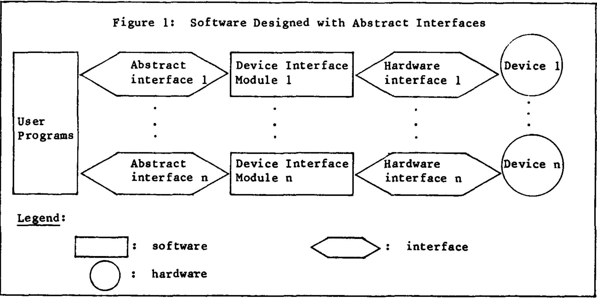
To avoid these problems it is common to divide the software into two groups of components: 1) the device interface modules containing the device-dependent code, and 2) the device-independent remainder of the software, including the user programs, so called because they use the device interface modules. Device interface modules provide virtual devices, that is, device-like capabilities that are partially implemented in software. For example, there is a virtual altimeter on the A-7 system. The virtual altimeter returns a value of type range, instead of the bit string read in from the actual sensor. The raw data is read, scaled, corrected, and flittered within the altimeter device interface module. This software structure is illustrated in Figure 1.
Design of device interface modules has the following goals:
- Confining changes
- Simplifying the rest of the software
- Enforcing disciplined use of resources
- Code sharing
- Efficient use of devices
Confining changes
Designing device interface modules is a special case of the information-hiding approach6; hardware interface details are hidden within modules that should be the only system components requiring changes when devices are modified or replaced by others that can perform the same basic functions. Problems in confining change are caused by three types of errors:
- The device interface module allows user programs to exploit special characteristics of a particular device so that user programs must be revised if the device is replaced.
- The virtual device lacks essential capabilities, so that user programs must access the actual device directly; again user programs must be revised if the device is replaced.
- Programs that are not necessarily device-dependent are included in the device interface module. As a result, the device interface module may need to be changed if the requirements change even if the device is not changed. Furthermore the module will be harder to change when the device is changed.
In summary, a device interface module will ideally
- be the only component that needs to change if a device is changed;
- not need to change unless the device is changed; and
- be relatively small and straightforward so that it is easy to change.
Simplifying the rest of the software
Embedded software is often hard to understand because its correctness depends on many arbitrary interface details. If these details are confined to device interface modules, user programs should be simpler, easier to write correctly, and easier to understand, than they would be if they used hardware interfaces directly.
Enforcing disciplined use of resources
Software reliability is enhanced when all programs that access a device adhere to certain disciplines, such as regular checks or undesired events7 and standard protocols for device sharing3. If these disciplines are built into the device interface modules, they are systematically enforced; programmers writing user programs need not be concerned with them.
Code sharing
When many programs access a device directly, they often contain similar subprograms performing the same device control functions. With device interface modules, this code need only be written once, saving programming, debugging, and testing time, and possibly computer storage.
Efficient use of devices
Independently written programs often cause devices to repeat actions unnecessarily. Centralizing device-access code should make it easier to avoid unnecessary operations.
To achieve these goals and avoid the mistakes mentioned earlier, the interface between a device interface module and user programs should be an abstract interface, as defined in the next section.
III. Definitions
- Interface: The interface between two programs consists of the set of assumptions that each programmer needs to make about the other program in order to demonstrate the correctness his own program. For convenience, we use the phrase “assumptions made by program A about program B,” to mean the properties of B that must be true in order for A to work properly. These assumptions are not limited to the calling sequences and parameter formats traditionally found in interface documents; they include additional information such as the meaning and limits of information exchanged, restrictions on the order of events, and expected behavior when undesired events occur. There is an analogous definition of the interface between a program and a device.
- Abstraction: An abstraction of a set of objects is a description that applies equally well to any one of them. Each object is an instance of the abstraction. For a non-trivial abstraction, there is a one-to-many relationship between the abstraction and the objects it describes. Differential equations are an example of a mathematical abstraction representing systems as diverse as electrical circuits and collections of springs and weights.
- An abstraction that is appropriate for a given purpose is easier to study than the actual system because it omits details that are not relevant for that purpose. A road map is an abstraction used to represent a road network; the graph represents the directions, relative lengths, and intersections of roads, but it does not show whether a road is made of asphalt or how is banked. It is far easier to find a good route by studying a road map than by exploring the actual roads.
- Any result obtained by studying an abstraction can be applied to any system represented by the same abstraction. Well-known graph theoretic results can be applied to a road map to determine the shortest route; the same methods have been applied o solve a wide variety of problems in other systems represented by directed graphs. Results may be misleading if they are obtained from an inappropriate abstraction, i.e., one that omits relevant details. For example, a road map is not sufficient to find the quickest route because it does not show other factors affecting driving time such as speed limits.
- Abstract interface: An abstract interface is an abstraction that represents more than one interface; it consists of the assumptions that are included in all of the interfaces that it represents. An abstract interface for a given type of device reveals some, but not all, properties of the actual device: it describes the common aspects of devices of that type, omitting the aspects that distinguish them from each other.
- Device interface module: A device interface module is a set of programs that translate between the abstract interface and the actual hardware interface. The implementation of this module is possible only if all assumptions in the abstract interface are true of the actual device.
- Secret: Secrets of a device interface module are assumptions about the actual device that user programs are not allowed to make. The secrets are information about the current device that need not be true of other devices with the same functions. Secrets must be taken into account somewhere in correctly working software; they are encapsulated in a device interface module.
- Undesired event assumptions: The interface between programs A and B includes both the assumptions made by A about B and the assumptions made by B about A. Systems can be designed so that only one of two programs relies on the other meeting its specifications. A program can be designed so that it does not rely on user programs using it correctly; it can check for improper uses and signal undesired events when they occur. However, the error checking and reporting require extra instructions. In development versions of the A-7 software, the device interface modules will assume that undesired events can occur; they will contain code to check for errors made by user programs. In the production version there will not be room for that error-checking. The device interface modules will assume that improper uses will not occur; the error-checking code will be omitted to make the system smaller and faster. If a problem occurs during operation of the production system, the error-checking will be reinserted to help locate the cause. The software will be written in such a way that the error checking code can be easily included or omitted when the program is assembled. This applies only to programming errors; error checks specified in the software requirements2 will never be omitted.
- Access functions: An access function is a program that is part of one module and may be called by programs in other modules. There are different kinds of access functions; some return information to the caller; others change the state of the module to which they belong.
- Events: Events are signals from a module to user programs indicating the occurrence of some state change within the module. They resemble hardware interrupts because they occur at unpredictable times and are not synchronized with the control flow of the user programs. In the A-7 system, modules will use a mechanism such as eventcounts8 to signal the occurrence of an event to user programs that are waiting for it to occur.
IV. Design Approach
This section describes a procedure for the design of abstract interfaces. The procedure is based on obtaining two partially redundant descriptions of the interface.
Description 1: Assumption List Characterizing the Virtual Device
For an application area such as avionics, many devices fall into standard types; all devices of a given type have many common characteristics. For example, as shown by advertisements in Aviation Week and Space Technology, computer panels vary little in the features seen by the pilot. For each hardware device, make a list of the characteristics that are not likely to change if the device is replaced by another device of the same type. To do so requires considerable study of devices that are available or being developed. The list of common characteristics is a description of the assumptions that user programs are allowed to make about the virtual device. The assumptions characterize device capabilities, modes, information requirements, behavior, and proper use of the device. A typical assumption might be:
The device produces information from which barometric altitude can be determined.
We are quite certain that only devices satisfying this assumption will replace the current barometric altitude sensor. Note that this assumption does not describe the form of the information, which may vary from one device to another.
Many assumptions will appear innocuous, but they must be recorded anyway. During the A-7 design reviews, some seemingly innocuous assumptions were found to be false
Description 2: Programming Constructs Embodying the Assumptions
The second description specifies the access functions and events that can be used by user programs. The access functions can be called by user programs to access the data or facility provided by the virtual device. For example, an interface might provide an access function GET_BAROALT, which returns a barometric altitude value. For each access function, we specify the values returned, the limitations, and the effect it has on the virtual device to which it belongs. User programs can also use the events in order to be signaled when the virtual device changes state. For example, user programs may need to be signaled when a virtual sensor is no longer operational.
Why Two Descriptions?
These two descriptions are partially redundant, i.e., the specifications for the programming constructs imply the assumptions. For example, specifications for the access function GET_BAROALT imply the assumption that the device provides information from which barometric altitude can be determined. The access function specifications provide additional information, namely the form of the data exchange between the device interface module and the user programs. For example, rather than provide barometric altitude directly, the device interface module might provide two or three quantities from which it could be computed. Such a design change would require a change int he function specification but not in the assumption list.
The two versions of the interface have different purposes: 1) the assumption list explicitly states assumptions that are implicit in the function specifications, making invalid assumptions easier to detect, and 2) the programming constructs can be used directly in user programs. It is essential that the two descriptions be consistent. The assumptions should be embodied clearly in the programming construct specifications, and the programming construct specifications should not imply any capabilities that aren’t stated in the assumption list. The assumption list should be reviewed by programmers, users, and hardware engineers who have the knowledge to check it for validity and generality. For example, the A-7 assumption were reviewed by system engineers and hardware engineers familiar with the A-7, A-6, and F-18 aircraft. Assumptions written in prose are easier for non-programmers to review. The specifications of the programming constructs should be reviewed by programmers who have worked with similar programs. These reviewers evaluate how well the abstract interface supports user programs and whether the device interface module can be implemented efficiently. The procedures and interface modules are described in device interface document4.
Design Procedure
Obtaining a correct and consistent dual description of an abstract interface is an interactive process. Although we attempted to list assumptions first, many of the necessary assumptions were quite subtle and only became apparent when we designed the programming constructs. Review of the assumption lists revealed errors in the programming constructs. The interfaces are the result of several cycles of review, both internally at NRL and by the A-7 maintenance team at the Naval Weapons Center (NWC). The first drafts were reviewed several times informally by the NRL A-7 team before they were submitted for an informal review at NWC. After further revisions within the NRL team, we held a formal review at NWC, resulting in the current version.
Illustration
As an example of this procedure, this section sketches the development of the abstract interface to the Air Data Computer (ADC). The ADC is a sensor that measure barometric altitude, true airspeed, and the mach number representation of airspeed.
Figures 2 through 4 are excerpted from successive versions of the ADC abstract interface. Each figure includes an assumption list and tables showing the associated programming constructs. These figures are not the complete specifications; other tables define system generation parameters and specify the ranges and resolutions of values. In the access function tables, “I” indicates an input parameter whose value is supplied by user programs; “O” indicates an output parameter whose value is returned by the ADC module.
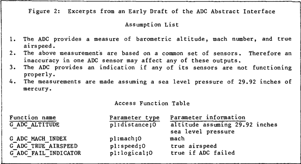
Although the early draft shown in Figure 2 seemed simple and reasonable to use, NRL and NWC reviewers found the following errors in it:
- The current ADC hardware and most replacement devices include a built-in test capability that cannot be accessed with the current interface.
- The description does not specify the values to be returned by the access functions while the ADC is in a failed state.
- The secretion does not specify the range of possible values for the measured quantities. The ranges are device-dependent, but they also affect user programs.
- The virtual ADC does not signal when it fails. User programs must poll the validity function to detect changes in reliability.
- The description does not make it clear whether the module performs device-dependent corrections to the raw sensor values.
After we corrected these errors, the interface shown in Figure 3 was reviewed formally at NWC.
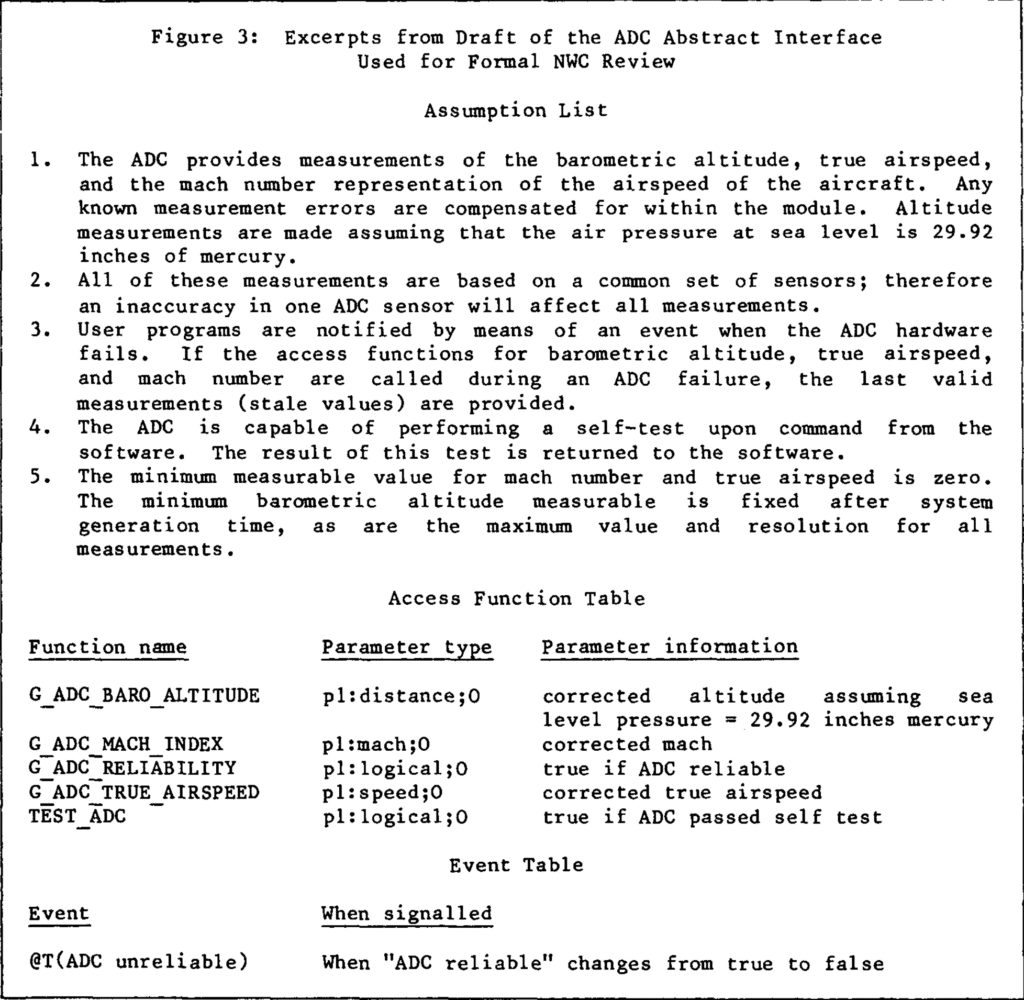
The following problems were pointed out.
- There is a device-dependent correction necessary for actual sea level pressure. The assumption of constant pressure is a poor one as it will force a device-dependent correction to be done by user programs. Future hardware may perform this correction automatically.
- Although the current hardware has one reliability indicator for all three values, replacement devices might not. In replacement devices the measurements might be made using independent sensors.
- We cannot assume that the minimum mach and true airspeed values are zero; some devices might not be capable of measuring such low values.
Figure 4 illustrates the product of the final revisions.

The development of the ADC abstract interface shows how the procedure supported our design efforts. Even the version in Figure 2 is a reasonable design; the errors it contains; the errors it contains are typical of errors made in embedded software. As a result of our procedure, the erroneous assumptions were written explicitly in a form meant for review, rather than left implicit. Unwise assumptions, which might have escaped our notice until after the code was written, were caught when they could be corrected relatively easily. The current version of the ADC interface may not be perfect, but it is much better than it would have been if we had not followed the procedure. Having two partially redundant descriptions of the interface was very important. We have examined our records and found that some errors were found in the assumption lists and others in the programming construct specifications. Seldom was the same error found in both versions.
V. Design Problems
The design considerations mentioned earlier serve as design guidelines and as standards for judging results. Although they help considerably, it is not always easy to apply them. Conflicts arise among three design goals: small device interface modules, device-independent user programs, and efficiency. What if user programs could use a device more efficiently if they could exploit assumptions that are not valid for all possible replacement devices? What if encapsulation of assumptions that are not always valid makes a device interface module slower or bigger? Acceptable compromises must be based on estimates of the likelihood of future changes. This section shows tradeoff problems and how we resolved them, attempting to minimize the expected cost of the software over its entire period of use.
Problem 1: Major variations among available devices
Deciding how much capability to include in a device interface module is particularly difficult when there are major differences among replacement devices. For example, new Inertial measurement Set (IMS) models produce present position data; other IMS devices produce velocity data; and the current A-7 IMS produces only velocity increments. In order to simulate an IMS that produces present position using the current IMS hardware, much of the navigation software would have to be inside the IMS device interface module; the result would be a very large module. One must choose between a) confining major changes within the device interface module, and b) keeping the device interface module small, so that minor but more likely changes are easier to make. Our compromise limits the range of devices represented by our virtual IMS, with the understanding that the remaining differences can be confined to a small set of user programs. Although our virtual IMS does not provide present position, it does provide velocities rather than velocity increments; the velocity increments are only used to compute velocities, and the velocities are widely used. The resulting virtual IMS is considerably eerier to use than the hardware IMS, yet we expect the IMS module to be reasonably small.
Problem 2: Devices with characteristics that change independently
Some devices can have several sets of characteristics that can change independently. For example, the Projected Map Display Set (PMDS) consists of a set of filmstrips and a hardware drive that positions a filmstrip in a display. The same drive could be used with new filmstrips containing maps in a different format, and the same filmstrips could be used with a different drive. According to the information-hiding principle, two independent sets of characteristics should be hidden in different modules so that they can be changed independently. However it is unnecessary for user programs to be aware of the separation. We chose to hide both sets of characteristics in one PMDS device interface module. The module will later be divided into two submodules, each insulated from changes in the other. Since the division is a secret of the PMDS device module, it is not apparent to user programs and is not presented in the interface specification.
Problem 3: Virtual device characteristics that are likely to change
Some changeable device characteristics must be revealed to user programs os that they can exploit the device effectively. Examples include measurement resolutions, the number of positions on switches, the device limitations such as a maximum displayable value. Although we would like user programs to be insulated from all device changes, they must behave differently if such characteristics change. For example, user programs controlling the PMDS must behave differently if the virtual PDMS provides maps of three different scales instead of just two. We represent such characteristics by symbolic constants. Both user programs and device programs are written in terms of symbolic constants rather than actual values. At system generation time, code can be generated by conditional macro expansion based on the actual values of the parameters.
We defined system generation parameters for the range and resolution of input and output data because 1) range and resolution are highly likely to vary among different devices; and 2) this information is needed by user programs in order to perform arithmetic accurately and efficiently. User programs written in terms of system generation parameters do not need to be rewritten if the parameter values change.
Initially we assumed that all parameter values would be known at system generation time; i.e., we explicitly assumed that whenever a replacement device is introduced, a new version of the program will be generated and deployed with the device. This assumption was questions at the design review. It is Navy policy not to have multiple versions of software in the fleet, even though equipment changes cannot be made simultaneously. Furthermore, we cannot require a new system generation if a new device breaks down and is temporarily replaced by a device of the old type. As a result, some of the parameters must be changeable at run-time. In theory this is true for any of the parameters; in fact, changeover problems are more likely for some devices than others. The cost of run-time variability also differs among devices, depending on whether the parameter can be used to control code generation so that run-time tests can be avoided. If changes are unlikely, we are reluctant to give up the efficiency advantages of binding the value at system generation time; if binding the value early causes no significant savings, we are reluctant to give up flexibility. We decided each case individually, using the following guidelines:
- Parameters with low cost for variability are treated as run-time variables, whatever the likelihood of change. Access functions to store and retrieve values appear in the module interface. See problem 4 for an additional problem about these parameters.
- Parameters with a low likelihood of change and a high cost for variability are bound at system generation time.
- For parameters with both a high likelihood of change and a high cost for variability, there are two possible solutions: a. They can be treated as run-time variables, with the option to bind them earlier by providing values at system generation time. This option allows us to delay the final choice until we have more information. b. We can find a conservative value that can be used for both devices, allowing use to bind the value at system generation time.
Problem 4: Device-dependent characteristics that vary at run-time
In some circumstances, user programs must handle device-dependent data. For example, when one IMS is replaced by another of the same type, the software must be adjusted because of manufacturing variations. The IMS software is parameterized so that it can be tailored to fit a particular piece of hardware. It is a requirement that we be able to change these parameters without reassembly. The parameters are entered at run-time through the computer panel. To receive the data, the IMS module provides access functions, which are called by the user programs that read in the panel data. Unfortunately, the existence of a run-time parameter such as drift rate reveals a secret of the IMS module, i.e., that the actual device drifts out of alignment. An additional drawback is that a replacement device might require different calibration data, requiring a change in the interface. We restrict use of these access functions so that the software making use of them is limited and easily identified. The restricted assumptions and access functions are called reconfiguration interfaces and are appended to the normal interfaces.
Problem 5: Interconnections between virtual devices
Ideally, virtual devices would be independent of each other, allowing the associated abstract interfaces to be designed independently of each other. However the A-7 system has device inter-dependencies introduced for hardware convenience. Some of these interdependencies are based on assumptions made by hardware designers about the software. For example, the Doppler and Ship Inertial Navigation Set might share a data path because someone assumed that the software will not need both devices simultaneously. We can hide the nature but not the existence of the interconnections; if we hid the interconnections, later changes in the user programs might result in attempts to access the devices incorrectly. The existence of interconnections is revealed in the assumption lists in terms of restrictions on the use of virtual devices. For example, there may be an assumption that two virtual devices cannot be used simultaneously. If the hardware interconnection is later removed, additional uses of one or both devices may become possible and desirable. Making such additions will inevitably require changes on both sides of the abstract interface: changes in user programs to exploit the new capabilities and changes in device interface modules to remove the restrictions. Since this cannot be avoided, there is no loss in revealing the restriction.
A similar problem can arise within a single device interface module if the present hardware does not allow two capabilities of the virtual device to be used at once. Again, we chose to reveal the restriction to user programs even though it might not be true of future devices.
Interconnection problems also arise where one device (the provider) provides information used by another (the receiver). There are two cases to consider:
- The computer can detect the failure of the provider. If so, the virtual receiver signals a failure when the provider fails, even if the actual receiver does not detect the failure. The device interface module for the receiver can simulate detection of the failure, thereby hiding the inter-connection.
- The computer cannot detect the failure of the provider. The undetectable failure of the provider must also be considered an undetectable failure of the receiver. People writing user programs that rely on the virtual receiver must be aware that undetectable failures are possible, but they need not be aware of the interconnection.”
Problem 6: Inconsistencies in the hardware interfaces
A hardware interface may provide similar functions in dissimilar ways. For example, the symbols on the HUD have three states: ON, OFF, and BLINKING. The HUD provides a hardware blink command for some symbols, but for others the software must simulate the blinking state by alternating the symbol between the ON and OFF states. Whenever the hardware interface provides some means to perform that action, we provide the feature consistently in the virtual device. The virtual HUD has commands to blink all symbols. However, when the hardware interface does not provide a way to perform an action, we were forced to reveal the inconsistency in the interface. For example, some H UD symbols have only two states: OFF and BLINKING.
Since there is no way to simulate the ON state, the virtual device cannot provide it. If the hardware limitation is removed in the future, the inconsistency can be removed from the virtual device. It is unavoidable that this changes oddly require changes on both sides of the abstract interface: changes in user programs to exploit the new capability and changes in the device interface module to implement it.
Problem 7: Switch nomenclature
Many of the switches do nothing more than set a bit that the computer can read. The label on a switch is an easily changed characteristic and could be hidden. We could name the switches anonymously (e.g. with integers) and use non-mnemonic names for the settings. However, a change in switch nomenclature will most likely be accompanied by a change in the requirements. The expected cost of working with non-mnemonic names, i.e., more errors, is high. In line with our basic principle of trying to minimize the expected cost of the software over the whole prior of use, we have chosen to reveal the nomenclature in switch names and mnemonic values for the switch settings. The names may suggest more than is actually stated in the assumptions; programmers are cautioned not to make assumptions about the switches beyond those that are explicitly stated in the interface documents.
Problem 8: Switches with hardware side-effects
When a switch also affects other devices, the meaning associated with it is not solely a software decision; major hardware changes would be required to use it for any other purpose. We consider such a switch part of the device that it affects, even if it is not physically located with the device. As far as user programs are concerned, the switch does not exist; the effects of the switch appear as changes in the operating mode of the virtual device. For example, the “Terrain Following” switch located on the master function panel affects the state of the Forward Looking Radar (FLR). Instead of appearing in the same interface description as the other master function switches, it is hidden within the FLR device interface module. User programs cannot read the switch, but they can call an access function that reveals the operating mode of the FLR.
Problem 9: Reporting changes in device state
User programs are often required to respond quickly to a change in device state. For example, user programs determining the current navigation mode need to know when the reliability status of the IMS sensor changes. The device interface modules can either 1) provide an access function reporting the current state of the device, or 2) signal the state-change event. The choice of a mechanism depends on whether user programs base decisions on the current state or wait for the state to change. If we based the design on the requirements of user programs, changes in their requirements might result in changes in the device interface module, violating the design goal that the device interface module should not need to be changed unless the device is changed. We chose to specify both mechanisms in every case, but plan to implement only the ones that are actually needed. Thus requirements changes may require changes to device interface modules, but these changes will consist of implementing previously specified features. By specifying possible additions in advance, we expect to reduce the cost of later reprogramming.
Problem 10: Devices requiring information from the software
Some hardware devices require information that is not calculated within the associated device interface module. For example, the current IMS device needs to know whether or not the aircraft is above 70 degrees (symbol) latitude, even though latitude is not calculated within The IMS module. One must chose between two ways to get the information to the device: 1) the device module can provide an access function that a user program calls in order to provide the information; or 2) programs in the device module can call other programs to get the information. Our decision is based on whether or not the information requirement I common to the class of replacement devices. If it is, the device interface module provides access functions for receiving the information. This solution results in added requirements for the rest of the software, and the user programs supplying the information must change if the information need changes. If the information need is peculiar to a particular hardware device, device interface programs call other programs to get the data. As long as the needed information is available from the rest of the system, no program outside the device interface module needs to change if the need for information disappears. We chose the later solution for The IMS example because not all IMS devices require a signal from the computer at 70 degrees (symbol) latitude.
Problem 11: Virtual devices that do not correspond to hardware devices
Initially, we assumed that there would be one virtual device for each hardware device. We found that modeling the virtual devices on the actual devices does not always result in clear interfaces. Some related capabilities are scattered among several hardware devices; some unrelated capabilities occur in the same device for physical convenience; other groupings can only be explained in terms of historical development. For example, weapons-related capabilities in the A-7 are scattered among several devices. Some weapons data comes from the device that controls weapon release, some is stored in tables, and some is provided by the pilot through switches. Additionally, the weapons release device fills two distinct roles: it is both a source of input data and the device that releases a weapon under computer control. Our final design includes one virtual device for weapons release and one for weapon data. The virtual devices are much simpler to understand than the actual devices. It is important not to be unduly influenced by the physical location of hardware units.
VI. Summary
We have applied a systematic procedure based on the abstract interface principle in the design of a substantial system. We find that the abstract interfaces make the system easier to code, and we expect to find that they make it easier to change in the future. Although the success of our abstract interface design cannot be judged until the A-7 implementation is complete and undergoing maintenance, our experiences so far have given us confidence to recommend the procedure to other designers.
This paper serves as an introduction to a more complete report4. Along with complete specifications for all the A-7 device interface modules, the report contains a description of the documentation organization and notation, a discussion of additional design problems, and a description of the procedures and questionnaires used for the major design review. The document is available from the authors.
VII. Acknowledgements
By reviewing interface specifications and discussing design problems, John Shore contributed greatly to the design of the A-7 abstract interfaces. Our collaborators at the Naval Weapons Center reviewed the A-7 abstract interface specifications, pointing out errors and helping us resolve the design problems. The authors also thank Edward Britton, Paul Clements, Constance Heitmeyer, and David Weiss for their careful reviewers of an earlier version.
References
- K. L. Heninger, “Specifying Software Requirements for Complex Systems: New Techniques and their Application,” IEEE Trans. Software Eng., vol. SE-6, pp. 2–13, Jan. 1980.
- K. L. Heninger, J. Kallander, D. L. Parnas, and J. E. Shore, Software Requirements for the A-7E Aircraft, Naval Research Lab., Washington, D.C., Memorandum Report 3876, 27 Nov. 1978.
- Hoare, C. A. R.; “Monitors: An Operating System Structuring Concept;” Commun. of ACM, vol. 17, no. 10; Oct. 1974.
- R. A. Parker, K. L. Heninger, D. L. Parnas, and J. E. Shore, Abstract Interface Specifications for the A-7E Device Interface Modules, Naval Research Lab. I Washington D.C., Memorandum Report 4385, 20 Nov. 1980.
- D. L. Parnas, Use of Abstract Interfaces in the Development of Software for Embedded Computer Systems, Naval Research Lab., Washington, D.C., Report 8047, 1977.
- D. L. Parnas, “On the Criteria to be Used in Decomposing Systems into Modules,” Commun. Ass. Comput. Mach., vol. 15, no. 12, p. 1053–1058, Dec. 1972.
- D. L. Parnas and H. Wuerges, “Response to Undesired Events in Software Systems,” Proc. Second Int. Conf. Software Eng., pp. 437–446, 1976.
- D. Reed and R. Kanodia, “Synchronization with Eventcounts and Sequencers,” Commun. Ass. Comput. Mach., v. 22, no. 2, pp. 115–123, Feb. 1979.
-
On leave from University of North Carolina at Chapel Hill. Also at IBM Corporation, Federal Systems Division, Bethesda, MD. ↩
If you like this paper, Autosar architecture (which is a common way of designing and developing automotive software for more than 15 years) should be also of great interest for you. You can download full spec of classic platform here: https://www.autosar.org/standards/classic-platform/classic-platform-440/
Thank you for the recommendation – definitely going to take a look!
Typo: “for one fo the A-7 device” -> “for one of the A-7 device”
This was a really great paper. It is interesting to see that such systems in the past were very carefully thought out in this way and have the same sorts of design decisions that we have today, even though there weren’t language constructs that explicitly embody the concepts of interfaces, etc. It really is fundamental to systems design and it gives joy to sort these things out and see the decisions have positive and simplifying effects and see the effect of the trade-offs. I really like thinking about these independent of the language used to implement them. Thank you for providing this!