
The facade pattern provides a unified (and often simplified) interface to a set of interfaces in a subsystem.
Mediator Pattern
The Mediator pattern is documented in Design Patterns: Elements of Reusable Object-Oriented Software, also known as the “Gang of Four” book. They describe the intent of the pattern as:
Define an object that encapsulates how a set of objects interact. Mediator promotes loose coupling by keeping objects from referring to each other explicitly, and it lets you vary their interaction independently.
Context
This pattern helps reduce (or eliminate) coupling between modules in the system by moving that coupling into a Mediator module or class. The Mediator is responsible for coordinating and controlling the interactions of the various modules.
Problem
A typical software design goal is to create modules that are independent and decoupled from other modules. However, to assemble complex system behaviors, you need modules to interact with each other. The most convenient way to develop complex behaviors is to have modules refer to each other in order to achieve the complex operation. This convenience makes the disparate modules tightly coupled, which means that a change in one part of the system will often cascade throughout the system. Wouldn’t it be preferable to have a way to coordinate the behavior of these modules without having them to be directly coupled together?
Forces
The Mediator pattern is balancing two competing forces: coupling and complexity. By increasing complexity (through the Mediator class), you can reduce the coupling between elements of a system. This is often desirable when the goal is to enable design for change, reusability, and/or testability.
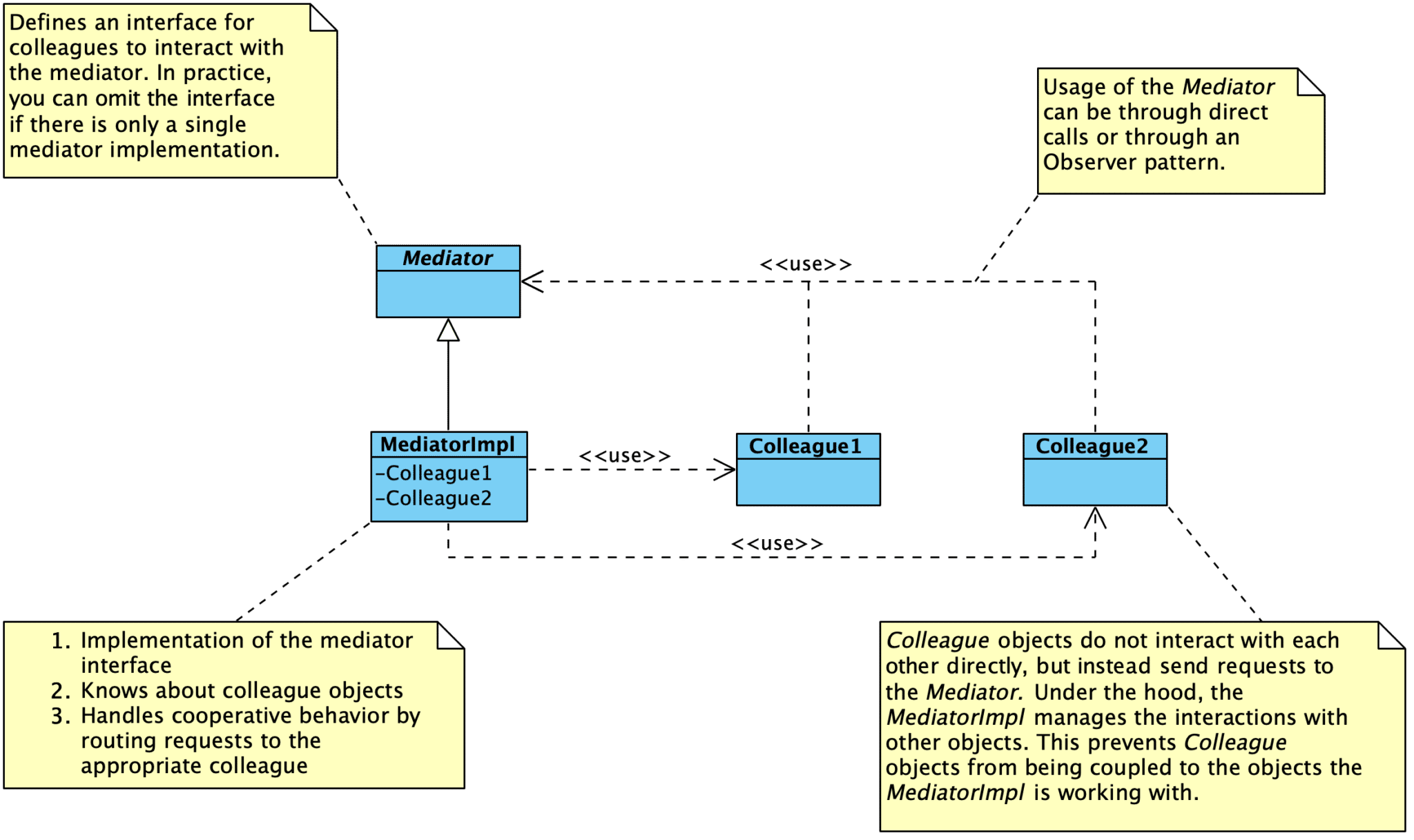
Solution
The goal of this pattern is to decouple modules or objects by constraining their interactions within a single Mediator. Instead of having objects interact with each other directly, the Mediator is responsible for coordinating the interactions between objects. Colleague objects know about the Mediator, but do not know about each other. The Mediator manages all interactions among Colleague objects.
Quote
You can avoid these [dependency] problems by encapsulating collective behavior in a separate mediator object. A mediator is responsible for coordinating and controlling the interactions of a group of objects. The mediator serves as an intermediary that keeps objects in the group from referring to each other explicitly. The objects only know the mediator, thereby reducing the number of interconnections.
–– Design Patterns
The Mediator pattern is also useful for coordinating “non-standard” functionality and configuration options that are provided by a specific implementation but not exposed through generic abstract interfaces. Tight coupling to a specific implementation can safely live in a Mediator. The rest of the program can use the generic interface.
Implementation Notes
- There is no need to define an abstract Mediator class when colleagues only work with a single mediator.
- Colleagues have to communicate with the mediator when an event of interest occurs.
- You can make direct calls.
- You can use the Observer pattern. When using the Observer pattern, Colleague classes act as subjects, sending notifications ot the mediator whenever they change state. The mediator responds by propagating the effects of the change to other colleagues.
- You can create a specialized notification interface in the Mediator. For instance, when communicating with the mediator, a colleague can pass itself as an argument, allowing the Mediator to identify the sender.
Consequences
This approach has three primary benefits:
- Interactions between objects are managed in a single place, instead of distributed across several objects. Changes in how objects interact only impact the Mediator module. This also helps us focus on interactions separately from the individual behavior of the objects.
- We create a one-to-many interaction set between the Mediator and its colleagues. This is much easier to conceptualize and manage than many-to-many interactions distributed among objects.
- Colleague modules are easier to reuse in other systems due to the reduced dependencies on other modules. We can independently reuse and vary the Mediator and its Colleagues.
One tradeoff with using the Mediator pattern is that we push most of the complexity in object interactions into the Mediator itself. This object runs the risk of becoming overly complex, but that can be managed.
Consequences:
- Localizes behavior that would otherwise be distributed among several objects – changes only need to happen in the Mediator only. Colleague classes can be reused without changes.
- Decouples colleagues from each other – you can vary and reuse colleague and Mediator classes independently.
- Simplifies interactions – replaces many-to-many interactions between objects with one-to-many interactions between the Mediator and colleagues. One-to-many interactions are easier to understand, maintain, and extend than many-to-many interactions.
- Abstracts how objects cooperate – lets you focus on how objects interact apart from their individual behavior. A Mediator can clarify how objects interact in a system.
- Centralizes control – Mediator pattern trades complexity of interaction for complexity in the mediator. This can make your Mediators harder to maintain.
Known Uses
Use the Mediator pattern when:
- A set of objects communicates in well-defined but complex ways. The resulting interdependencies are unstructured and difficult to understand.
- Reusing an object is difficult because it refers to and communicates with many other objects.
- A behavior that’s distributed between several classes should be customizable without a lot of subclassing.
For embedded software, a hardware abstraction layer (HAL) or board support package (BSP) can also be examples of the Facade and Mediator patterns (which it is depends on the design). Fundamentally, the goal of a HAL or BSP is to provide Facade that higher software layers can use to interact with the underlying hardware. If the components managed by the HAL or BSP can also use the provided interfaces, we end up with a Mediator.
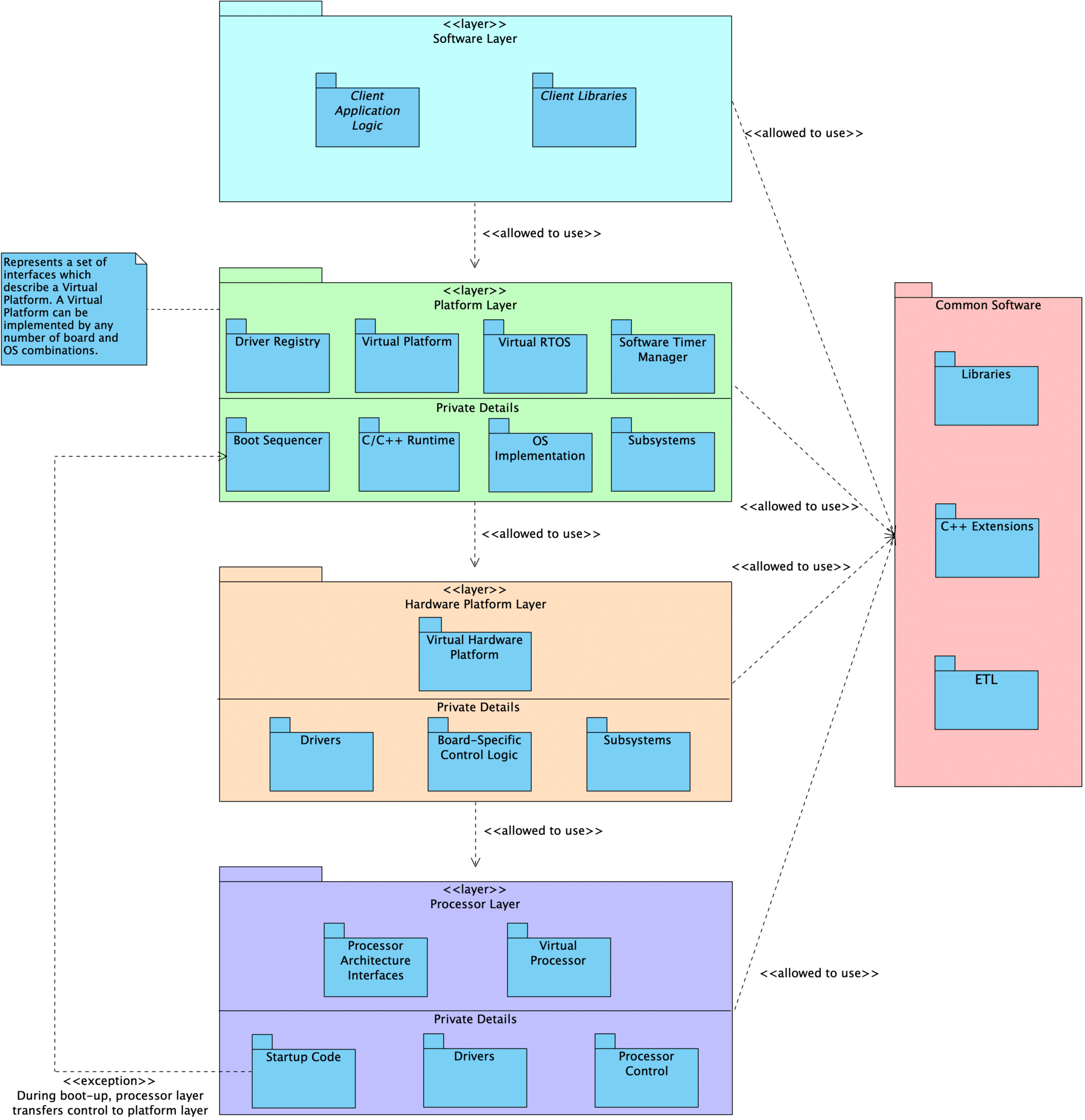
In our own standard embedded program design, we create three core Facade/Mediator layers with different responsibilities: Processor, HardwarePlatform, and Platform.
- The Hardware Platform contains all the details about what hardware is on the board, what peripherals are hooked up to what, and the various configuration details for those particular parts.
- The Hardware Platform has access to specific implementations and can invoke APIs that are note exposed through the abstract interfaces.
- There are common interfaces that apply to all Hardware Platforms. These can be used by other parts of the system, such as the boot process.
- The Hardware Platform provides its own general interface for use by Platform modules.
- Above the HW platform, none of the specific details about the underlying hardware are known, other than the generic interfaces provided by the HW platform layer itself and the generic interfaces to drivers that are automatically registered in a central driver registry.
- The Platform contains a Hardware Platform, as well as other software-level details: OS initialization, heap initialization, language feature setup, etc.
- Like the Hardware Platform, it is responsible for configuring and coordinating platform-specific details that should be kept hidden from the rest of the program.
- There are common interfaces that apply to all Platforms. These can be used by other parts of the system, such as the boot process.
- The Platform provides its own general interface for use by application-level modules.
These are described in further detail in the following locations:
- Embedded Artistry’s Software Layering Strategy
- Managing Coupling with the Mediator and Facade Patterns
- emvbm-core Architectural Layer View
Variants
- In their book Patterns in the Machine: A Software Engineering Guide to Embedded Development, the Wayne brothers describe an architectural approach using two different patterns: “Main Pattern” and “Model Points”. In our view, this is an application of the Mediator pattern. Different modules interact through Model Points to send and receive data – the modules know about the semantics of the Model Points they must interact with, but not what is on the other side of that Model Point. In this sense, Model Points are serving as a Mediator. The Main Pattern can also be viewed as a variation on Mediator, just viewed from a step above the Model Points. This pattern describes having a section of code that knows about concrete instances of modules, configures them, and connects them together via Model Points. All of the complexity for the system is contained in the specific implementation of the Main Pattern, while the modules themselves remain independent and unaware of other modules in the system.
Related Patterns
- The Facade pattern is an alternative to Mediator in some contexts, and the two may be combined together.
Differentiating Mediator and Facade
When you think about the Mediator and Facade patterns alongside each other, they may seem quite similar. Fundamentally, both patterns are about managing interactions between modules.
The primary difference is in the type of interaction between modules.
The Facade Pattern abstracts a subsystem to provide a more convenient interface or to shield users from directly interfacing with subsystem modules. The interaction flows in one direction: users make a request of the Facade, and the Facade makes requests of the subsystem modules. In fact, subsystem modules do not know about the existence of the Facade!
The Mediator pattern primarily enables cooperative behavior while keeping modules decoupled. The Mediator pattern allows us to centralize coordination activities that do not belong in the individual modules. Unlike the Facade pattern, Colleagues are aware of the existence of the Mediator and communicate with the mediator instead of directly with each other. The Mediator itself communicates with Colleagues to fulfill requests.
In practice, the lines between these two patterns can blur. Sometimes you are able to create clearly defined Facades and Mediators. In other cases, the resulting design is a blend of the two patterns.
For example, consider a Facade for a power subsystem. The Facade provides a general interface for handling power-related activities, and it uses the subsystem objects to fulfill the requests.
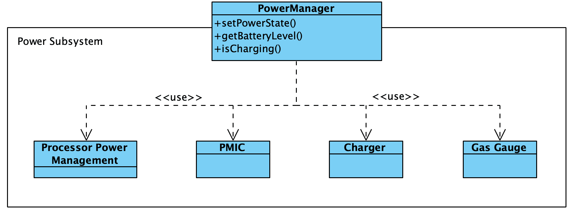
However, we might need a more complex power management module. What if the setPowerState() function interacted with other drivers to control when they are turned on and off? And what if drivers themselves can trigger power state changes through the power management module in response to specific events?
In this case, we end up with something that resembles a blend between the two patterns rather than a pure Mediator or pure Facade.

References
- Wikipedia: Mediator Pattern
- Managing Coupling with the Mediator and Facade Patterns – Embedded Artistry
- Patterns in the Machine: A Software Engineering Guide to Embedded Development by John Taylor and Wayne Taylor
- Prototyping and Design for Change: Lightweight Architectural Strategies
Any code which lives outside of our tightly coupled mediator modules must remain generic.
We want to eliminate the use of platform-specific code from our generic modules. This includes vendor SDK driver interfaces, RTOS-specific APIs, direct register accesses, and platform-specific debugging functionality. These items prevent us from easily porting our code from one platform to another when the time comes.
To keep code portable, only use standard language features, your custom abstractions, or portable libraries.
- Managing Coupling with the Mediator and Facade Patterns
Define an object that encapsulates how a set of objects interact. Mediator promotes loose coupling by keeping objects from referring to each other explicitly, and it lets you vary their interaction independently.
- Coupling
- Design Patterns: Elements of Reusable Object-Oriented Software by Gamma et al.
However, Mediator’s purpose is to abstract arbitrary communication between colleague objects, often centralizing functionality that doesn’t belong in any one of them. A mediator’s colleagues are aware of and communicate with the mediator instead of communicating with each other directly. In contrast, a facade merely abstracts the interface to subsystem objects to make them easier to use; it doesn’t define new functionality, and subsystem classes don’t know about it.
- Design Patterns: Elements of Reusable Object-Oriented Software by Gamma et al.
Resource Acquisition is Initialization [RAII]
An object-oriented idiom, where holding a resource is tied to an object’s lifetime. Allocation happen during construction, and release happens during destruction.
Abstract Interface
An “abstract interface” is a higher-order abstraction that can represent one or more concrete implementations. An abstract interface defines the required minimum contract that all suitable implementations must satisfy: function signatures, preconditions, postconditions, and behavioral guarantees. What is revealed is the contract callers can rely on; what is hidden are internal state, algorithms, and platform dependencies. Note that the interface captures what all valid implementations must provide, not the union of every possible feature.
Abstract interfaces can take many forms, all of which are mechanisms for expressing the same thing: a contract that callers can rely on and implementations must satisfy.
- a straightforward header-defined interface
- a collection of function pointers
- an abstract base class
- Rust traits
- C++ concepts or templates
Abstract interfaces are used to improve the changeability of software. Programs are written against the interface, keeping details about the underlying implementation secret. The fundamental goal is to be able to swap different implementations without needing to change components that interact with the interface.
Courses
Blog Posts
- How Our Approach to Abstract Interfaces Has Changed Over the Years
- Virtual Devices in Embedded Systems Software
- Practical Decoupling Techniques Applied to a C-based Radio Driver
Papers
- For information on designing abstract interfaces for device drivers, see the paper “A Procedure for Designing Abstract Interfaces for Device Interface Modules” by David Parnas et al. . This paper provides a procedure for creating abstract interfaces, discusses common design challenges with creating abstract interfaces for device drivers, and provides examples from a real-world avionics program.
- Abstract Interface Specifications for the A-7E Device Interface Module by David Parnas et al.
- Use of Abstract Interfaces in the Development of Software for Embedded Computer Systems by David Parnas
- Paper: Towards a New Model of Abstraction in Software Engineering by Gregor Kiczales
Selected Quotes
- Abstract Interface Specifications for the A-7E Device Interface Module by Parker, Heninger, and Parnas
Interface: The interface between two programs consists of the set of assumptions that each programmer needs to make about the other program in order to demonstrate the correctness of his own program. For convenience, we use the phrase “assumptions made by program A about program B,” to mean the properties of B that must be true in order for A to work properly. These assumptions are not limited to the calling sequences and parameter formats traditionally found in interface documents; they include additional information such as the meaning and limits of information exchanged, restrictions on the order of events, and expected behavior when undesired events (ref (7)) occur. There is an analogous definition of the interface between a program and a device.
Abstract interface: An abstract interface is an abstraction that represents more than one interface; it consists of the assumptions that are included in all of the interfaces that it represents. An abstract interface for a given type of device reveals some, but not all, properties of the actual device: it describes the common aspects of devices of that type, omitting the aspects that distinguish them from each other.